
Let's continue our consideration of relay protective devices. These devices switch off the load when the line voltage goes above or below a certain threshold.
We have already discussed the features of such chargers and why they cannot always replace UPSs or voltage stabilizers, as well as the main points of choice. In this review, we will consider six new models of single-phase group voltage relays offered by Russian companies.
These devices can be individual, installed between a specific load and an outlet, or group, designed for higher operating currents and installed in an electrical panel on a DIN rail. Over the years, the model range has been updated, and in this review we will look at the new items.
When discussing previous reviews, the issue of protecting devices from impulse noise and interference, including lightning strikes, was often raised. However, this is a separate task that requires an integrated approach and corresponding costs. In this review, we only consider specific devices with specific functions.
Some readers ask why these particular models are being considered and not others. The answer is simple: we describe what we were able to get into our laboratory and focus on the available samples.
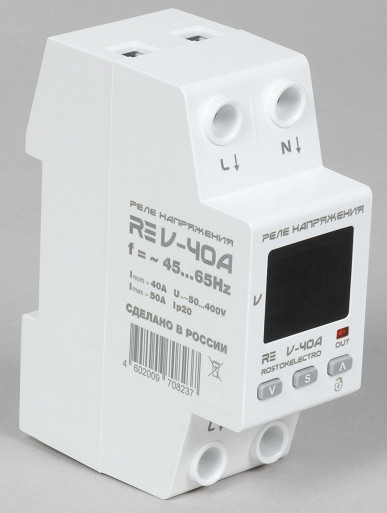
Voltage relay "Rostok-Electro"
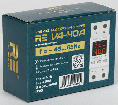
This company previously offered products under the DigiTop brand, but starting in late 2023, it will launch new lines of voltage relays on the market under the RE brand. One of them monitors only the line voltage (RE V), while the other also monitors the current consumed by connected loads (RE VA).
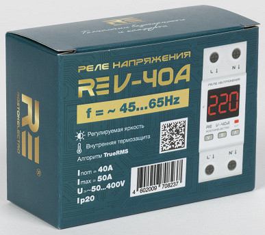
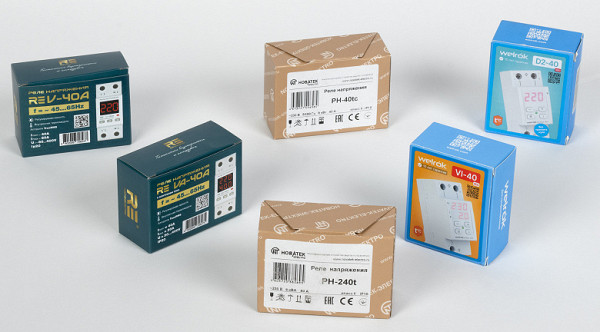
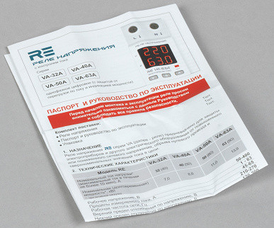
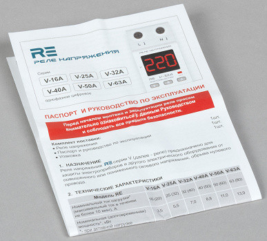
The voltage relays are presented in colorfully designed packaging, which is individual for each model and clearly displays their main characteristics. Each device is supplied with detailed, high-quality instructions in color format.
Warranty period 60 months (5 years).
RE VA-40A: capabilities, technical characteristics
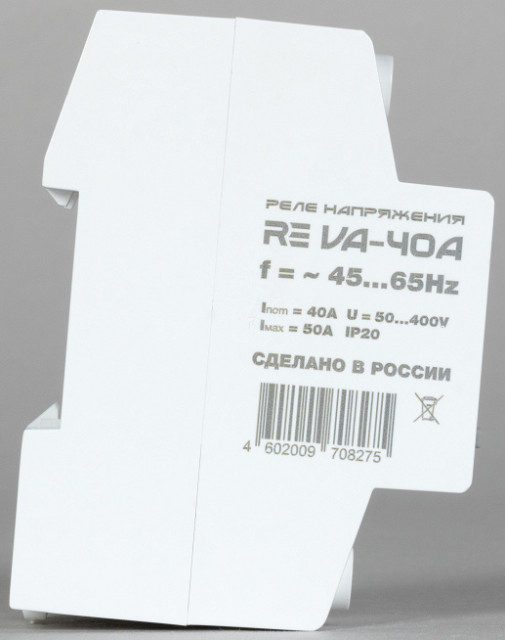
There are four devices in the line, equipped with a built-in voltmeter and ammeter; they differ in their current/power limits.
| Model RE | VA-32A | VA-40A | VA-50A | VA-63A |
|---|---|---|---|---|
| Rated load current (active), A | 32 | 40 | 50 | 63 |
| Maximum current (for no more than 10 minutes), A | 40 | 50 | 60 | 80 |
| Rated long-term power (active load), kW | 7.0 | 8.8 | 11.0 | 13.9 |
All of these chargers provide not only voltage control, but also overcurrent protection with an adjustable threshold.
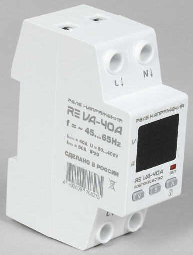
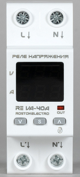
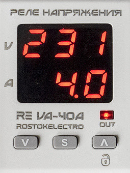
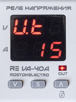
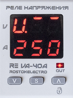
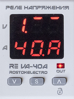
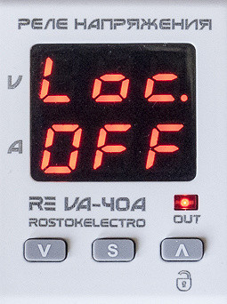
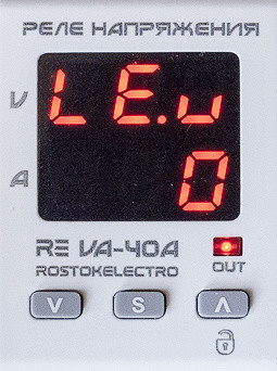
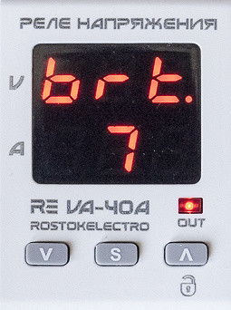
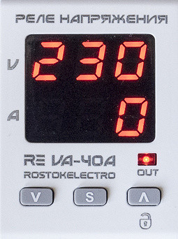
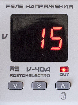
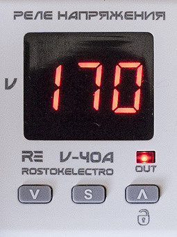
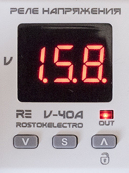
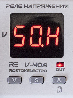
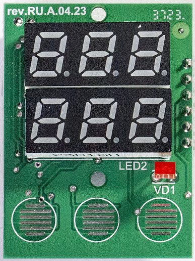
The voltmeter and ammeter indicators are represented by LED seven-segment three-digit displays with a symbol 7.1 mm (0.28 inches) high, red, located in two lines. The device has nine selectable brightness levels and displays the input voltage when the output is off. There is also a separate red LED to indicate voltage is being supplied to the loads.

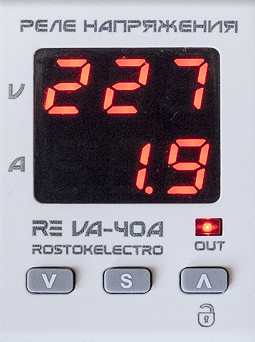
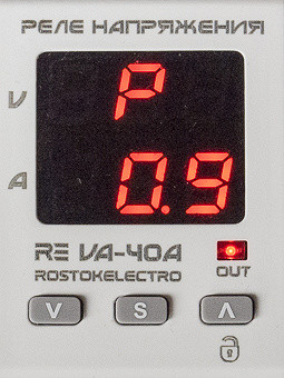
You can also view the load power (it is calculated from the voltage and current readings) by pressing the down arrow button; values less than 0.5 kW are displayed as “0”.
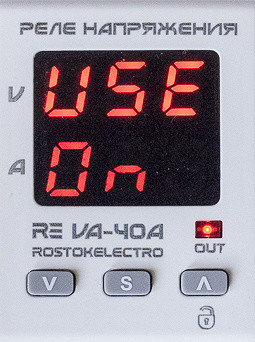
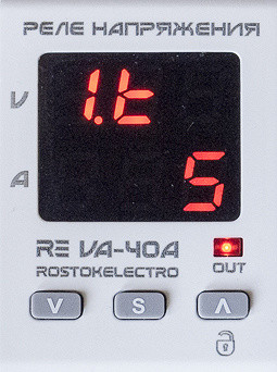
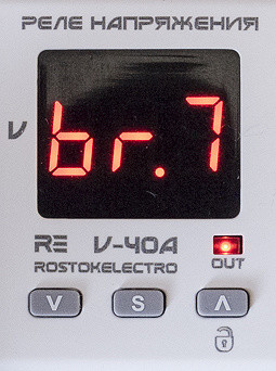
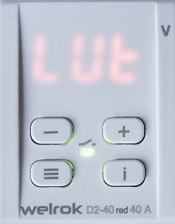
If the names of some parameters in the menu do not fit into three characters, they are displayed as a creeping line.
The following parameters are declared:
| Operating voltage, V | 50—400 | |
|---|---|---|
| Limits of measured current, A | 1—63 | |
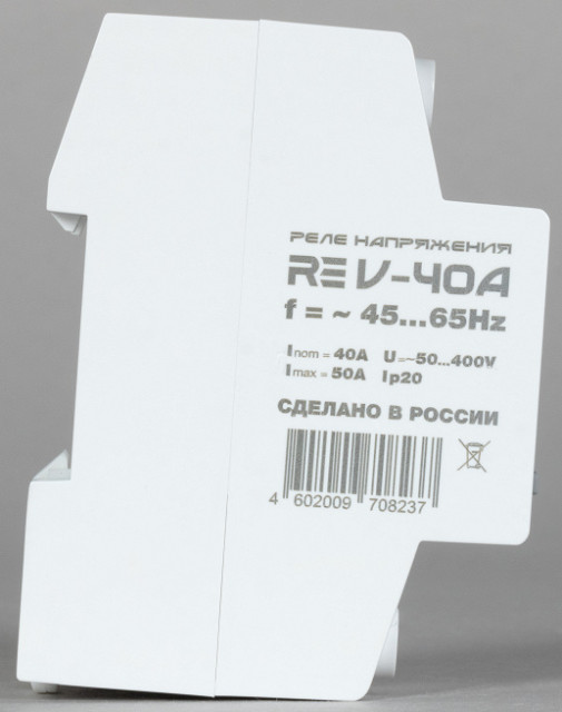
| Operating frequency of the network, Hz | 45—65 | |
| Upper voltage cut-off limit, V | 210—270 | |
| Lower voltage shutdown limit, V | 120—200 | |
| Voltage hysteresis, V *) | 1 | |
| Shutdown time at upper voltage limit, sec | ≤0.02 | |
| Shutdown time at lower voltage limit, sec, at voltage | 120-170 V | ≤1 |
| <120V | ≤0.02 | |
| Current trip limit | from 1 A to I nom , step 1 A | |
| Number of current trips | 1—10 or ∞ | |
| Shutdown time, sec, at current | I nom < I measured < I max | 600 |
| I max < I measured < 2 I nom | 5 | |
| I measured ≥ 2 I nom | 0.02 | |
| Voltmeter error, % | ≤1 | |
| Current measurement error (from 1 to 63 A), % | ≤2 | |
| Own power consumption, W | RE VA-32A | ≤2.5 |
| RE VA-40/50/63A | ≤1.5 | |
| Device protection degree | IP20 | |
| Maximum wire cross-section, mm² | 10 | |
| Tightening torque of terminal screws, Nm | 2.2 ±0.2 | |
| Operating temperatures, °C | −25… +50 | |
| Overall dimensions, mm | 90 × 35 × 67 |
*) The hysteresis value is not in the specification; we clarified it with the developers.
The measurements are carried out using the True RMS algorithm, which ensures the same accuracy both for a pure sine wave and for a signal with significant nonlinear distortions, as can be the case at the output of many generators.
Voltage thresholds are set in 1-volt increments, and current thresholds in 1-amp increments. The turn-on delay time is separately adjustable for current and voltage protection in the range from 5 to 600 seconds in 5 second increments.
The load current limiting mode in the RE VA memory is presented in several options, each of which determines the shutdown time depending on the level of current excess. For example, for the RE VA-40A model, if the current is in the range from 40 to 50 amperes (overload up to 25%), then the shutdown will occur after 10 minutes. For currents from 50 to 80 amperes — after 5 seconds, and if the current exceeds 80 A, the load will be turned off in no more than 20 milliseconds.
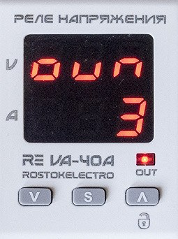
In addition, it is possible to configure the output blocking in case of current overload, which will need to be reset manually. You can specify the number of activations for blocking — from one to ten, or disable this function.
To handle very large inrush currents, greater than 20 ms, the current limiting mode can be disabled completely, but it is recommended to install a circuit breaker in front of the charger, which is more suitable for handling short-term currents.
Accuracy measurements are frequency dependent: the True RMS algorithm assumes 200 samples per 20 ms timer, corresponding to one cycle at 50 Hz. If the network frequency is higher (for example, the period is less than 20 ms), the measurement cycle will cover part of the next period, and the measurement accuracy will decrease, which will affect the voltage and current thresholds of the memory.
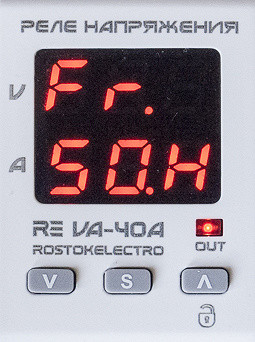
Therefore, two settings are provided:
- “50.H” (i.e. 50 Hz) for operation from a regular power supply, measurement cycle 20 ms, shutdown delays in accordance with the parameter table;
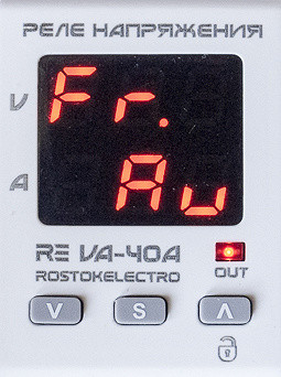
- «Auto» for sources with unstable frequency, for example, generators; A 200-sample timer adjusts to the input signal period and changes the measurement period to maintain measurement accuracy. The device can operate at frequencies from approximately 40 to 70 Hz, but outside this range the protection will operate.
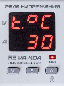
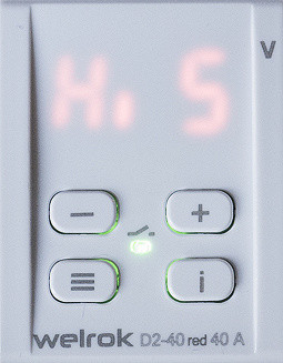
Overheating protection is also provided: when the temperature inside the charger reaches 70°C, the load is turned off and “Hot” is displayed on the indicator. The load will turn on automatically after cooling to 60°C. The current temperature and firmware version can be viewed through the built-in menu.
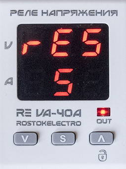
The voltage of the last operation is stored in the memory, which can also be viewed through the menu.
The buttons can be locked.
For other models discussed in the review, the stated maximum wire cross-section is 16 mm², while in this case the stated smaller value is 10 mm². This difference raises questions, given that the terminals are the same size for all six samples. It is possible that the lower value is simply a typo, although it is present in the instructions for the RE VA and RE V lines.
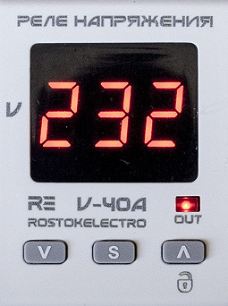
RE V-40A: capabilities, technical characteristics
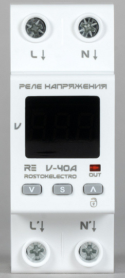
There are no longer four, but six devices in this line, differing in current/power limits. They only have a voltmeter and do not provide overcurrent protection. Frequency accounting is the same as in the RE VA line; there is also overheating protection.
| Model RE | V-16A | V-25A | V-32A | V-40A | V-50A | V-63A |
|---|---|---|---|---|---|---|
| Rated load current (active), A | 16 | 25 | 32 | 40 | 50 | 63 |
| Maximum current (for no more than 10 minutes), A | 20 | 32 | 40 | 50 | 60 | 80 |
| Rated long-term power (active load), kW | 3.5 | 5.5 | 7.0 | 8.8 | 11.0 | 13.9 |
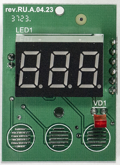
They look exactly like the RE VA models, the indicator is also red, but in the absence of an ammeter, the symbols are larger (their height is 9.1 mm or 0.36 inches) and are therefore better readable from a distance — compare:
The list of declared parameters is shorter for obvious reasons:
| Operating voltage, V | 50—400 | |
|---|---|---|
| Operating frequency of the network, Hz | 45—65 | |
| Upper voltage cut-off limit, V | 210—270 | |
| Lower voltage shutdown limit, V | 120—200 | |
| Voltage hysteresis, V *) | 1 | |
| Shutdown time at upper voltage limit, sec | ≤0.02 | |
| Shutdown time at lower voltage limit, sec, at voltage | 120-170 V | ≤1 |
| <120V | ≤0.02 | |
| Voltmeter error, % | ≤1 | |
| Own power consumption, W | RE VA-16/25/32A | ≤2.5 |
| RE VA-40/50/63A | ≤1.5 | |
| Device protection degree | IP20 | |
| Maximum wire cross-section, mm² | 10 | |
| Tightening torque of terminal screws, Nm | 2.2 ±0.2 | |
| Operating temperatures, °C | −25… +50 | |
| Overall dimensions, mm | 90 × 35 × 67 |
*) The hysteresis value is not in the specification; we clarified it with the developers.
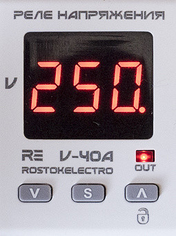
They look exactly like the RE VA models, the indicator is also red, but in the absence of an ammeter, the symbols are larger (their height is 9.1 mm or 0.36 inches) and are therefore better readable from a distance — compare:
General assessment of structures
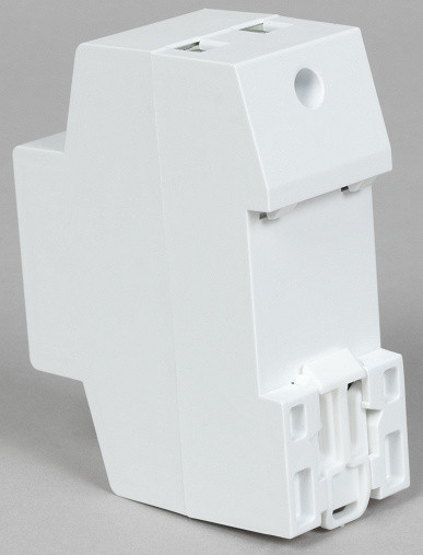
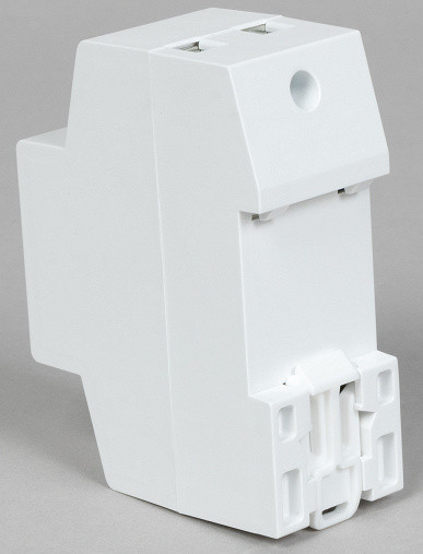
The standard width of one module mounted on a 35 mm DIN rail is 17.5 mm (DIN 43880). However, each of the RE V/VA models reviewed is 35mm wide, meaning it will take up exactly two rack spaces. Compared to previously known analogues, which took up three places, this can be an advantage when installed in panels with a large number of components, especially when placed in compact plastic boxes.
The indicator is covered with a light filter, which ensures very good visibility of the symbols.
The latch does not have a spring, so when installing the charger on a DIN rail, it must first be pulled out slightly and then pushed in firmly to secure it. At the same time, the shank of the latch extends slightly beyond the dimensions of the housing, which makes installation operations convenient even with tight installation using a flat-head screwdriver.
The mounting on the rail is reliable, and there is no backlash with moderate force.
The connection diagram is available only in the product passport, but it is not indicated on the case, which is quite normal, since the relay opens the phase circuit. To connect, it is enough to connect the L and N wires of the power supply to the upper contacts of the charger, and the corresponding load wires to the lower ones, where the symbols are clearly visible.
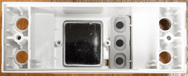
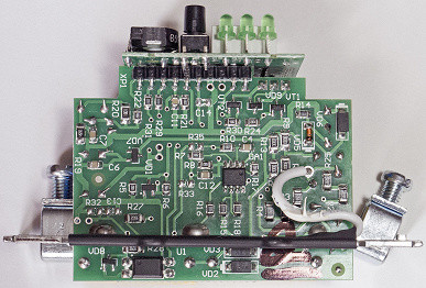
Access to the insides of the charger is very simple: just remove two self-tapping screws on the bottom, after first pulling out the latch.
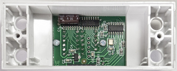
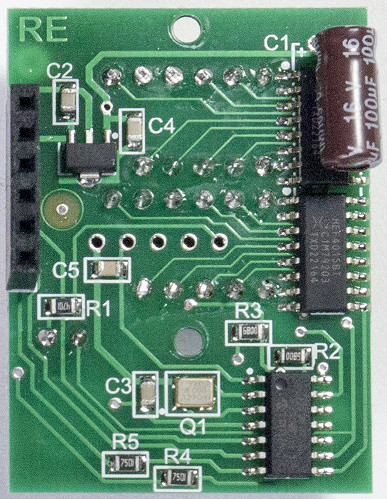
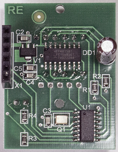
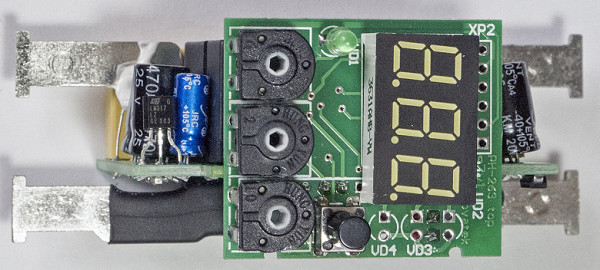
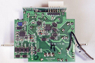
Due to the «double-din» design, two boards with electronic components (power and low-current) are arranged in the shape of the letter «L». These boards are connected to each other using a connector.
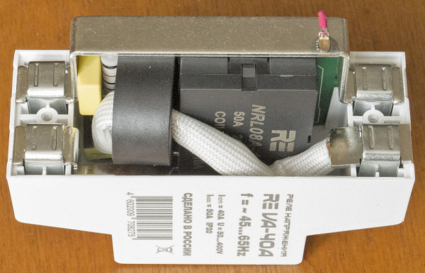
The first thing that attracts attention is the neutral bus, which frames the upper part of the power board and merges into a single whole with the fixed parts of the input and output terminals N. It is made of a non-magnetic alloy, has a width of 10 mm and a thickness of 1.4 mm. It is attached to the board with a thin wire using welding.
Since the neutral line is not used for switching, there is no need to connect both terminals N. It is enough to simply connect one of them to the appropriate terminal block or cross-module using a wire of any cross-section sufficient to power the control circuits of the charger, the consumption of which does not exceed several tens of milliamps.
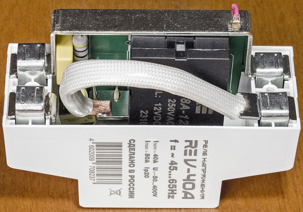
A flexible copper busbar with a large cross-section is welded to the fixed part of the input terminal L. In RE VA models, such a bus passes through a linear current sensor, indicated in the photo by a black ring next to the electromagnetic relay. RE V models do not have such a sensor. This bus is connected by welding to an external relay contact, from which the conductor goes to the board to power the charger electronics.
The output terminal L, being the second contact of the relay, has a complex shape. It is also made of copper, but with a thickness of 1.0 mm, and is similar to the material of the N bus.
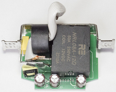
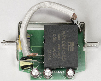
The device uses an NRL08A-12D electromagnetic relay, probably based on NCR or another manufacturer's product, but with additional improvements and the «RE» marking. There is currently no available datasheet for this relay, but it can be assumed that it is a polarized relay with a maximum operating current of 50 amps. For a 40-amp model, this is enough, but we don’t know about the currents provided by the relays in the 50- and 63-amp chargers, since we didn’t come across such models.
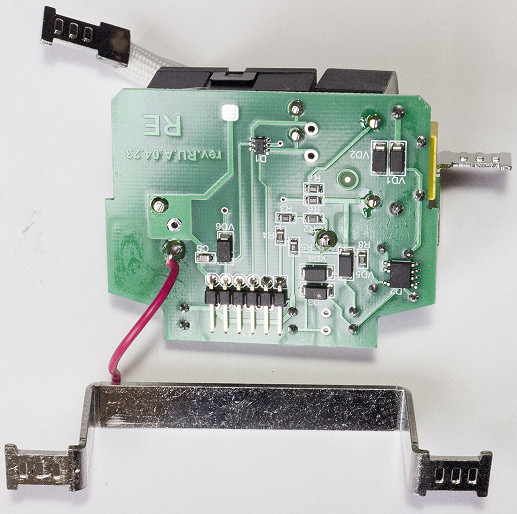
The control part of the device is powered by a BP3166B ASIC, which uses a transformer circuit to provide galvanic isolation. To suppress electromagnetic interference in the control circuits of the device, a capacitor X2 with a capacity of 0.01 μF is used.
The control part of the device is powered by a BP3166B ASIC, which uses a transformer circuit to provide galvanic isolation. To suppress electromagnetic interference in the control circuits of the device, a capacitor X2 with a capacity of 0.01 μF is used.
The control buttons are made in membrane style.
The installation was done neatly, without excess solder or traces of flux. The manufacturing quality of the plastic cases is high.
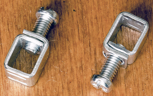
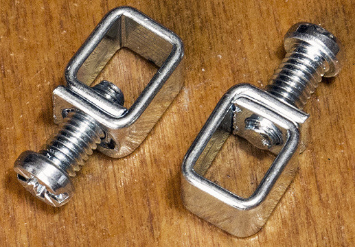
The moving parts of the terminals are made of 1.4 mm thick steel and secured with M5 screws. The contact surfaces are flat, but have small stamped projections.
Voltage relay "Novatek-Electro"
The products of this company were previously known under the name of the Volt Control line, but in the new samples that we received, this name is no longer used.
If previously we had Volt Control RN-113 relays, which differed significantly from others in the configuration of the control panel and connection method, then in the new products only the panel remained unusual. In addition, the new products are much more compact: instead of three spaces on the DIN rail, they take up only two.


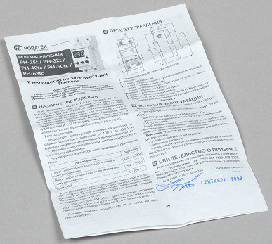
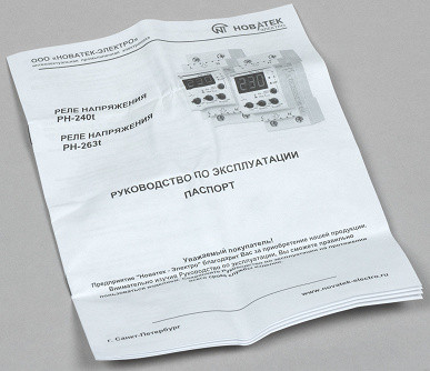
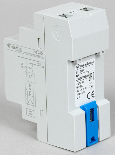
The packaging for the new products is the same as for the company's previous products — modest boxes with the contents indicated on a sticker. The chargers are also additionally packaged in a zip bag. The instructions are quite detailed and high quality, but are printed in monochrome.
Warranty period 120 months (10 years).
RN-240t: capabilities, technical characteristics
We have the model designated in the title, as well as another one labeled RN-263t. The differences between them are transparent in the table (we cannot unambiguously interpret some parameters, so we leave them as in the official documentation).
| Model | RN-240t | RN-263t |
|---|---|---|
| Maximum switching current with active load, A | 40 | 63 |
| Maximum switched power at active load, kW | 9 | 14 |
| Maximum switching power with active-inductive load (cos φ = 0.4), kW | 1.6 | 2.0 |
| Maximum permissible alternating voltage, V | 250 | |
| Life time | mechanical, times, no less | 500 thousand |
| electric, times, no less | 20 thousand | 10 thousand |
Other parameters are the same for both models:
| Rated supply voltage, V | 230 | |
|---|---|---|
| Network frequency, Hz | 47—65 | |
| Rated insulation voltage, V | 450 | |
| Rated impulse withstand voltage, kV | 2.5 | |
| Operation threshold for U min , V | 160—230 | |
| Operation threshold for U max , V | 240—290 | |
| Current threshold | from 1 A to I nom | |
| Active power measurement accuracy, %, no worse | 5 | |
| Current measurement accuracy, %, no worse | 2.5 | |
| Voltage measurement accuracy in the range 120-350 V, %, no worse | 2 | |
| Ready time, seconds, no more | 0.8 | |
| Own power consumption, W, no more | 2 | |
| Voltages at which operability remains, V | minimum | 130 |
| maximum | 450 | |
| Protection response time according to U max , seconds | 1 | |
| Shutdown delay when voltage exceeds 430 V and duration is more than 1.5 ms, seconds, no more | 0.05 | |
| Shutdown delay when the voltage rises more than 30 V from the setting for U max , seconds | 0.12 | |
| Protection response time according to U min , seconds | 7 | |
| Shutdown delay when voltage drops below 145 V, seconds | 0.25 | |
| Accuracy of determining the voltage threshold, V | 3 | |
| Voltage hysteresis, V | 4 | |
| Protection response time for I max , seconds | 5 | |
| Degree of protection | IP10 | |
| Wire cross-section for connection to terminals, mm² | 0.5—16.0 | |
| Tightening torque of terminal screws, Nm | 2 ±0.2 | |
| Operating temperatures, °C | −35… +55 | |
| Overall dimensions, mm | 90×36×60 |
These chargers provide not only voltage control, but also overcurrent protection with an adjustable threshold.
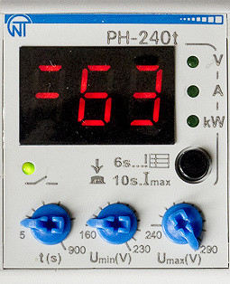
The current threshold is set by a button in 1 ampere increments, in the range from 1 to 63 A for the RN-240t model, although the parameter table indicates “up to Inom”. There is no information about the maximum current threshold setting in the RN-263t.
The memory stores information about the last five triggers.
The auto-restart delay time is only adjustable for voltages between 5 and 900 seconds. Auto-return to operating state is not provided for current protection. You will have to disconnect the charger with a circuit breaker installed in front of it, eliminate the cause of the accident and connect it again.
The supply network frequency is not taken into account.
Overheating protection works differently than in RE V/VA: if the temperature exceeds 85 °C, the load is switched off and the “Ert” symbols flash on the indicator. After this, you will have to manually turn off the charger, check the causes of overheating, wait for it to cool down and turn it on again.
It is difficult to compare which scheme is better — with auto-return after overload/overheating in Rostock-Electro products or without it in Novatek-Electro. Various arguments can be made from the point of view of safety and practicality. Let us remind you that auto-recovery after an overload in RE VA can be adjusted or disabled, but in RN-240t/263t there is only manual recovery.
The RN-240t/263t does not have a three-stage circuit for current shutdown, as in RE VA products: operation occurs 5 seconds after the threshold is exceeded, and the minimum value of such an excess is not specified. This may be less safe and practical than RE VA.
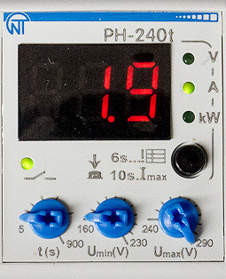
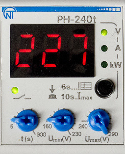
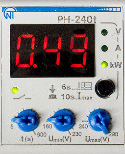
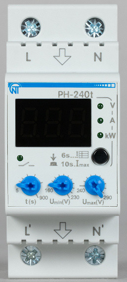
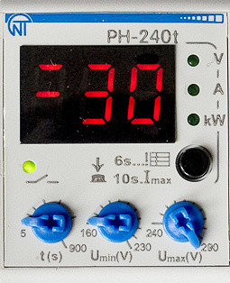
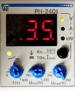
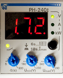
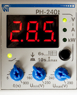
The indicator is a seven-segment, three-digit LED display with a character height of 9.1 mm (0.36 inches), emitting red light. It is common to display three parameters: voltage, load current and active power. However, each of these options can be displayed separately and selected using a button that is also used to perform several other functions. The selected display mode is remembered when the power is removed and is confirmed by tiny green LEDs with the corresponding designation.
When the device output is turned off, the display shows the input voltage. Additionally, there is a separate green LED indicating the presence of voltage supply to the load.
Although the voltage sensing algorithm is not explicitly stated, it is assumed that using the True RMS method would have noted this. Consequently, if there are significant nonlinear distortions in the network, the measurement accuracy may be worse than indicated in the table. The measuring ranges are as follows:
| Controllable range | Measuring range | ||
|---|---|---|---|
| Active power, kW | — | 0.1—14 | |
| Load current, A | RN-240t | 1—40 | 0.5—80 |
| RN-263t | 1—63 | ||
| Input voltage, V | 160—290 | 120—350 |
Low load powers (for RN-240t — 100 W or even a little less) are indeed displayed, but the error can be significant.
There is no information about the ability to view the firmware version.
When setting values, the indicator additionally displays flashing dots.
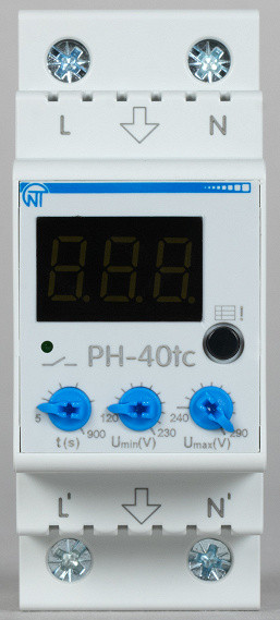
RN-40tc: capabilities, technical characteristics
Functionally, this is an analogue of RE V — only the voltage is controlled. And also in the line there are a number of models:
| Model | RN-25tc | RN-32tc | RN-40tc | RN-50tc | RN-63tc |
|---|---|---|---|---|---|
| Maximum switching current with active load, A | 25 | 32 | 40 | 50 | 63 |
| Maximum switched power at active load, kW | 5 | 7 | 9 | eleven | 14 |
| Maximum switching power with active-inductive load (cos φ = 0.4), kW | 1.2 | 1.4 | 1.6 | 1.8 | 2.0 |
| Maximum permissible alternating voltage, V | 275 | ||||
| Life time | mechanical, times, no less | 500 thousand | |||
| electric, times, no less | 20 thousand | 10 thousand | 20 thousand | 10 thousand | 10 thousand |
Other parameters are the same for all models:
| Rated supply voltage, V | 230 | |
|---|---|---|
| Network frequency, Hz | 47—65 | |
| Rated insulation voltage, V | 450 | |
| Rated impulse withstand voltage, kV | 2.5 | |
| Operation threshold for U min , V | 120—230 | |
| Operation threshold for U max , V | 240—290 | |
| Voltage measurement accuracy in the range 100-350 V, %, no worse | 2 | |
| Ready time, seconds, no more | 0.8 | |
| Own power consumption, W, no more | 2 | |
| Voltages at which operability remains, V | minimum | 90 |
| maximum | 450 | |
| Protection response time according to U max , seconds | 1 | |
| Shutdown delay when voltage exceeds 430 V and duration is more than 1.5 ms, seconds, no more | 0.05 | |
| Shutdown delay when the voltage rises more than 30 V from the setting for U max , seconds | 0.12 | |
| Protection response time according to U min , seconds | 7 | |
| Shutdown delay when voltage drops below 100 V, seconds | 0.25 | |
| Accuracy of determining the voltage threshold, V | 3 | |
| Voltage hysteresis, V | 4 | |
| Degree of protection | IP10 | |
| Wire cross-section for connection to terminals, mm² | 0.5—16.0 | |
| Tightening torque of terminal screws, Nm | 2 ±0.2 | |
| Operating temperatures, °C | −35… +55 | |
| Overall dimensions, mm | 90×36×60 |
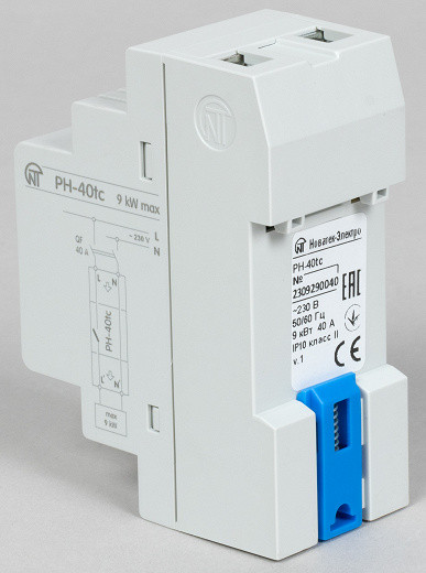
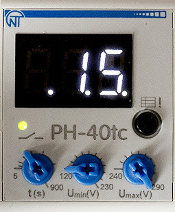
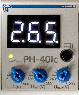
Externally, these models are the same as the PH-240t/263t, only there are no LEDs indicating the displayed parameter, since it is the only one, and the button only serves to enter the menu.

Overheating protection is provided and operates according to the scheme already described. However, for models with currents of 40 amperes and above, it is especially noted that the temperature of each contact is controlled (the presence and method of implementation will be discussed in detail below).
In addition, the device stores information about the last five accidents.
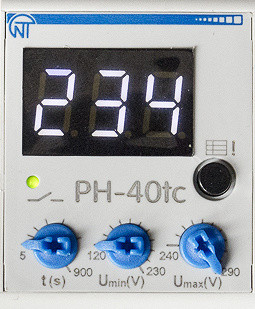
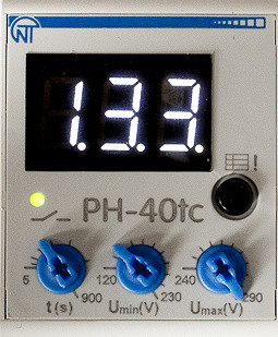
The indicator size is the same as the PH-240t/263t models — the height of the characters is 9.1 mm (0.36 inches), but the color of the indicator is white. It should be noted that it is unclear whether this is a characteristic feature of this line, since there is no information about the possibility of using red indicators.
General assessment of structures
The width of both versions of the Novatek-Electro charger is slightly larger than the DIN 43880 standard, but this small excess is unlikely to be critical in most cases.
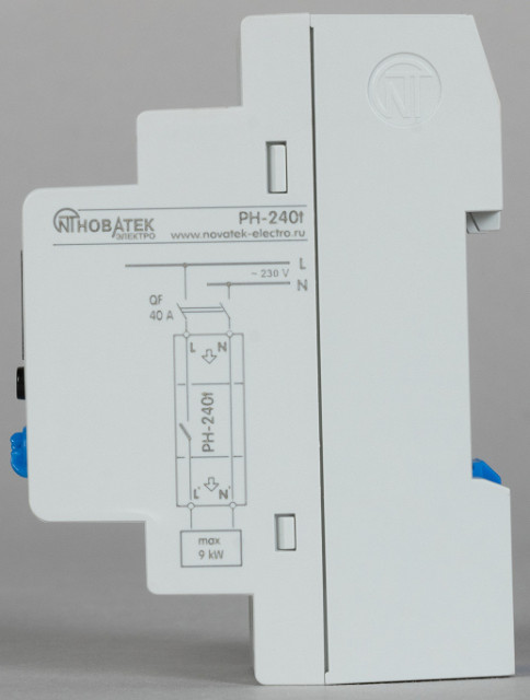
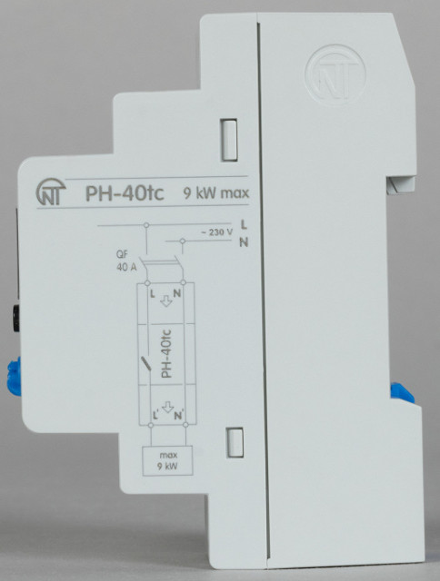
The connection diagram is presented on the side surface of the case and is identical to the diagram of products from Rostock-Electro: the relay opens the phase circuit, so it is enough to connect the L and N wires of the supply network to the upper contacts of the charger, and the corresponding load circuits to the lower ones (both categories have clear and clearly visible symbols).
The indicator is covered with a light filter, which ensures very good visibility of the symbols.
The latch here is spring-loaded, which makes installation on a firmly fixed metal rail more convenient. In some cases, it may work on its own after pressing the lower part of the charger housing. However, when removing or installing it in a plastic box, it must first be slightly pulled back and then released. To do this, you will need to insert a screwdriver into the slot at an angle of about 40-45 degrees, which can be somewhat inconvenient during tight installation.
Nevertheless, the fixation on the rail itself turns out to be as reliable as that of products from Rostock-Electro.
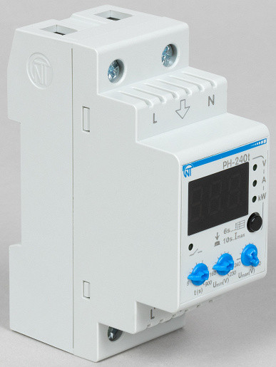
РН-240t
Setting the automatic turn-on delay and voltage thresholds is not done using buttons, but using potentiometers. However, the outer knobs of these potentiometers are too small, making them difficult to use comfortably. Their small size makes them difficult to grasp with your fingers, especially for those used to larger handles. To make adjustments, you will need to have a small screwdriver on hand that is compatible with the potentiometer slot. The voltage setting resolution is 1 volt, but it can be difficult to adjust resistors for such small changes in the threshold. In contrast, the delay is set in one second increments, which is more convenient. In general, these difficulties are not serious, since such adjustments are not carried out very often. However, it should be noted that the reliability and durability of potentiometers is usually lower than that of pushbuttons.
РН-40tc
The current threshold in models RN-240t/263t is set using a button through the menu.
The parts of the case are fastened not with screws, but with latches, which makes disassembly a little more difficult than that of the charger from Rostock-Electro, but this does not cause any particular difficulties. Although in general there is space for one screw, in our samples it turned out to be empty.
РН-40tc
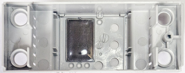
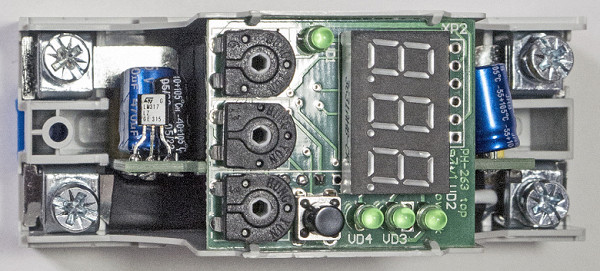
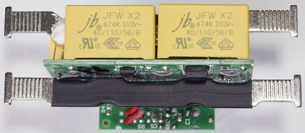
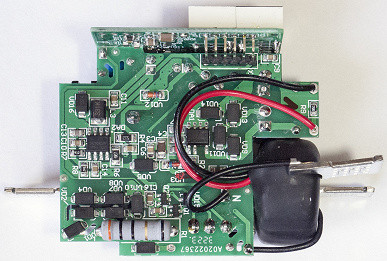
The design is also two-board, where the boards are arranged in the form of the letter “T”, their connection is made without the possibility of disconnection.
The neutral bus is also integrated with the fixed parts of the N input and output terminals, but in this case it is a linear structure rather than a U-shape. The tire is made of a non-magnetic alloy, its width varies from 7 to 8 mm, and its thickness is 1.5 mm. A thin wire runs from the neutral bus to the board. Most of the bus is covered with heat shrink tubing, which also covers the junction of said wire.
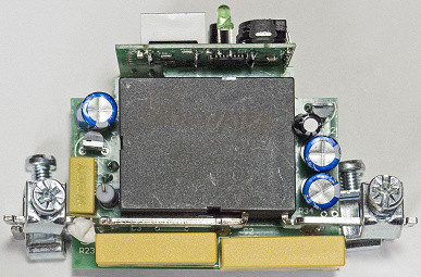
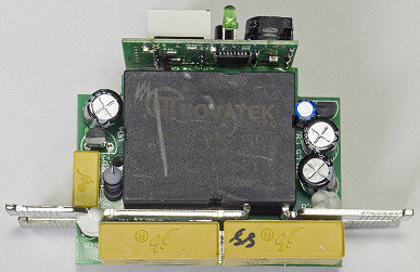
The charger electronics are powered using a quenching capacitor. In this case, two parallel-connected capacitors X2 are used: 0.33 μF at 310 V for the RN-240t model and 0.47 μF for the RN-40tc model. In addition, the circuit contains a thyristor and an LM317 stabilizer. To protect the internal circuits of the charger from electromagnetic interference, a capacitor X2 with a capacity of 0.1 μF is provided.
Switching is carried out using a polarized relay NRL709BC-12D in a custom design. The external contacts of the relay serve as fixed parts of the input and output terminals of the phase, and have a specific shape. The relay is designed for current up to 80 amperes, and its contacts are made of AgSnO2 material. For the original relay model, it is stated that it is mechanically capable of making at least 105 operations, and electrically — 104 (however, other values may be specified for the memory due to custom execution). The relay actuation and release time does not exceed 20 ms.
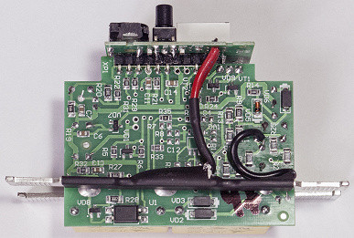
Models RN-240t/263t do not have a contactless current sensor. Instead, a part of the input bus L approximately 25 mm long, which is one of the relay contacts, is used for measurement. The signal is then processed by the MCP602-I/SN dual operational amplifier. With this approach, measurement accuracy is not critical since it is more of an indicator than an accurate meter. Permissible deviations are indicated in the specification and are up to 2.5 percent.
These models have one temperature sensor, which is glued to the phase input terminal. There is space on the board next to the output terminal for a second sensor, but it is not used. The RN-40tc model contains three sensors: on each of the phase terminals and in the middle of the neutral bus.
The control is carried out by an Atmel Mega88PA microcontroller, and the button is mechanical.
РН-240t
The installation was done neatly, without excess solder or traces of unwashed flux. The manufacturing quality of the plastic parts of the cases is high, but the absence of a self-tapping screw in the place intended for it seems strange.
The moving parts of the terminals are made of 1.5 mm thick steel and are secured with M5 screws. The contact surfaces are flat, but have small stamped projections.
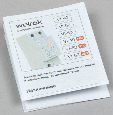
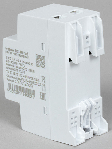
Welrok voltage relay
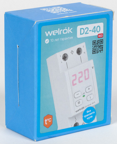
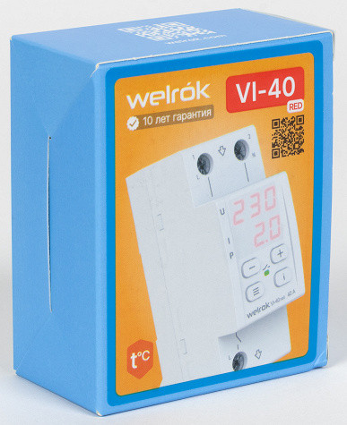
The chargers are sold in colorfully designed packaging, individual for each model, and are supplied with detailed instructions — in color and with good printing quality.
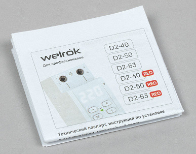
In addition to the presence or absence of current control (for models designated “VI” or “D2”, respectively), the choice can be made according to two additional criteria: the color of the indicator (red or white, reflected in the name as “red”) and the number of neutral terminals (one or two, indicating “with zero transit” for the second option, which costs several percent more).
In addition, there is a “VIP” line, which is distinguished by the simultaneous display of voltage, current and load power.
The warranty period is 120 months (10 years).
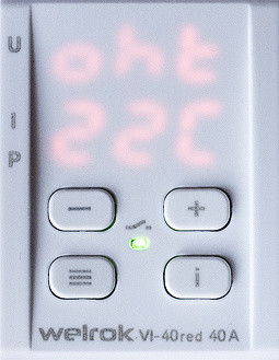
VI-40: capabilities, technical characteristics
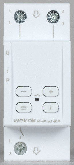
There are three models in the line for different current limits, each with the variations just mentioned; we received a 40-amp sample with a red indicator and no zero transit.
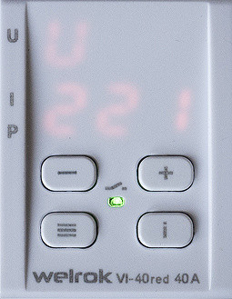
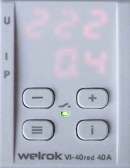
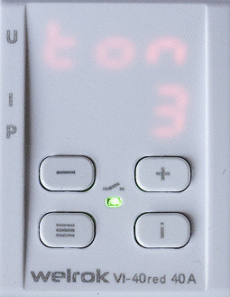
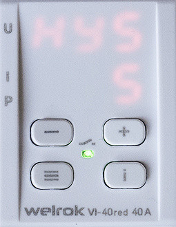
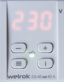
Note: do not rush to swear at the pictures below with poorly visible indications, but read the section dedicated to Welrok products to the end.
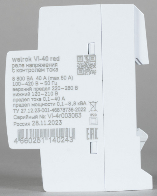
We reproduce the parameters as in the official description, although there are questions about some positions.
| Model | VI-40 / 40 red | VI-50 / 50 red | VI-63 / 63 red |
|---|---|---|---|
| Rated load current for category AC-1 *) , A | 40 | 50 | 63 |
| Maximum current (for no more than 10 minutes), A | 50 | 60 | 80 |
| Rated load power for category AC-1 *) , VA | 8800 | 11000 | 13900 |
| Main current limit, A | 0.1—40 | 0.1—50 | 0.1—63 |
| Power limitation (total), kVA | 8.8 | 11.0 | 13.9 |
*) i.e. for loads with a power factor of at least 0.95
Other parameters are the same for all models:
| Current measurement accuracy, A | 0.5–63 ±0.2 | |
|---|---|---|
| Voltage limits, V | upper | 220—280 |
| lower | 120—210 | |
| Shutdown time when overvoltage, seconds | ≤0.03 | |
| Shutdown time when decreasing, seconds | >120 V | 0.1—10 |
| <120V | ≤0.03 | |
| Supply voltage, V | 100—420 | |
| Energy consumption, kWh/month | ≤0.35 *) | |
| Number of switchings | under load | ≥10000 |
| without load | ≥500000 | |
| Relay type | polarized | |
| Degree of protection | IP20 | |
| Wire cross-section for connection to terminals, mm² | ≤16 | |
| Tightening torque of terminal screws, Nm | 2.4 | |
| Operating temperatures, °C | −5… +45 | |
| Overall dimensions, mm | 85 × 36 × 66 |
*) if recalculated, the power consumption is within 0.5 watts
Measurements are made using the True RMS algorithm (this is stated on the company’s website, we did not find anything like this in the instructions).
In addition to setting voltage shutdown thresholds, you can also limit either the current or power (one of the two) of the load, setting the corresponding values up to the rated current or power.
Current thresholds can be set in increments of 0.1 A. The question of the need for such granularity given the stated measurement error of ±0.2 A remains open. The same can be said about setting the power limit in steps of 0.1 kVA. Even more puzzling are the minimum thresholds of 0.1 A / 0.1 kVA.
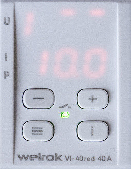
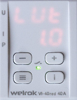
For all VI samples, the factory current setting is 10 amperes, which is very small compared to the nominal value, so it should be adjusted immediately.
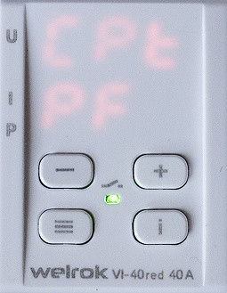
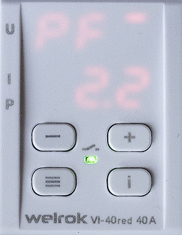
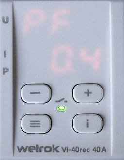
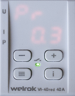
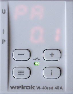
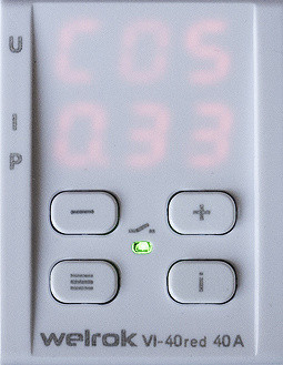
The frequency of the supply network is not subject to control, however, among the displayed parameters there are not only voltage and current: you can also see values for the load power — apparent (“PF”), active (“PA”) and reactive (“Pr”), as well as for cos φ (“COS”).
Additionally you can set:
- Start-up delay after an accident — from 3 to 999 seconds, in 3-second increments.
- Load shutdown delay when the upper current/power limit is exceeded — from 0 to 240 seconds, in 1 second increments.
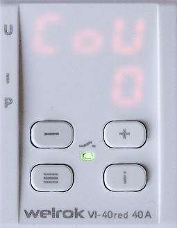
- The maximum number of consecutive operations due to excess current, power or voltage is from 1 to 5 times.
There are no special questions regarding the first point, but it is worth adding a few clarifications regarding the other two.
There are no direct indications in the instructions about the minimum excess of the current/power threshold, after which it triggers or begins counting the delay. However, there are additional settings related to the current limit, the values of which sometimes raise questions. For example, there is a «lower current limit» parameter, which is described as «set the maximum value of the motor's no-load current.» Perhaps this function is useful in certain situations, but its description in the instructions seems unsuccessful and difficult to understand for most memory users.
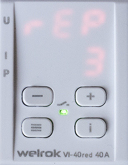
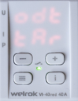
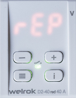
Voltage trips are considered consecutive if they occur within 20 seconds of each other. However, no such additional comments are provided regarding current/power. Once the preset number of such trips has been exceeded, the load is switched off and the message «rEP» appears on the display. To continue working, you must press any button.
Welrok VI models offer the most extensive range of settings among all participants in the review. In addition to the features already mentioned, included:
- Correction of voltage readings by ±20 V in 1 V steps if they diverge from the reference voltmeter. The charger will operate in accordance with the adjusted readings.
- Correction of current readings by ±20% (for example, ±2 A for a value of 10 A), in steps of 0.1 A, if they do not correspond to the reference ammeter. This function is available when there is a load greater than 1 A.
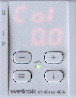
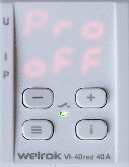
- «Professional» voltage shutdown model with different shutdown times depending on the voltage level.
- Load turn-on delay type: counting begins either from the moment the voltage is restored or from the moment the relay is activated.
- Adjustable hysteresis from 0 to 5 Volts in 1 V steps. A value of 0 may not be very useful, it is better to set a value other than zero.
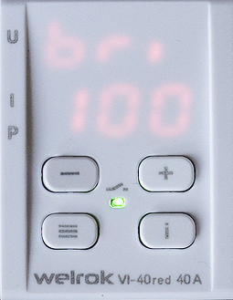
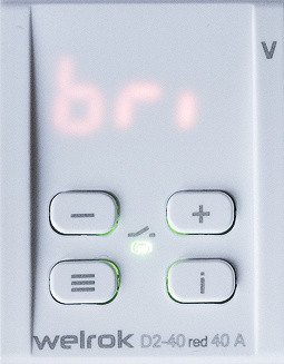
- Brightness adjustment from 0 to 100 percent in steps of 10%. When set to «0», the indicator will operate at maximum brightness for 30 seconds after pressing any button, and then turn off or remain on continuously after an emergency event until the cause is eliminated.
- Non-volatile memory stores information about 100 accidents.
No mention is made of power supply frequency control.
The buttons may be locked.
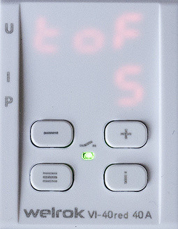
Overheating protection is also provided: if the temperature inside the case exceeds 80 °C, the load is turned off and the “oht” symbols flash on the indicator. After the temperature drops to 60 °C, the output will be automatically turned on, but if the thermal protection is triggered more than five times a day, the charger will turn off the load and lock, displaying “oht” without blinking. When the temperature drops below 60 °C and a dot appears on the indicator, the relay can be unlocked by pressing any button.
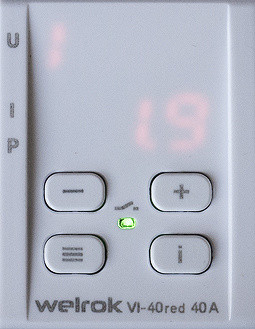
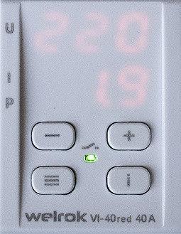
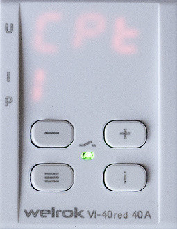
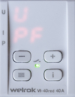
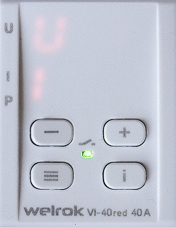
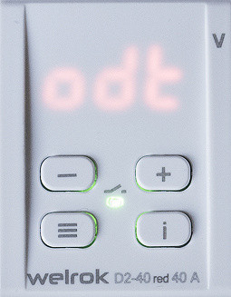
The height of the characters on the indicator is 7.1 mm (0.28 inches), which simultaneously displays voltage and either current or load power (selectable in the corresponding menu item). However, it is not always obvious whether the bottom line is current or power. To clarify this, just briefly press the lower left button: the prompt “U” and “I” (current), or “U” and “PF” (power) will appear.
Models from the Welrok VIP line are clearer in this regard: they have three lines to display voltage, current and power, while the height of the symbols remains the same. However, the number of control buttons has been reduced to two, which makes the control process a little more complicated.
Small power values (the first hundred watts) are displayed as zero, while the current for such loads will be displayed correctly.
When the output is turned off, the indicator displays the input voltage. In addition, there is a separate green LED indicating the presence of voltage on the load.
To view the firmware version, you can hold down the «i» button for 6 seconds, and the current temperature inside the case for 16 seconds.
The description mentions “the ability to evenly distribute the load across phases,” but it is worth noting that the voltage relay itself does not perform any load distribution. Its function is only to turn off when overloaded. However, any charger with current/power display can help estimate the load connected to different phases and then redistribute it to achieve a more even distribution.
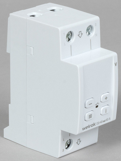
D2-40: capabilities, technical characteristics
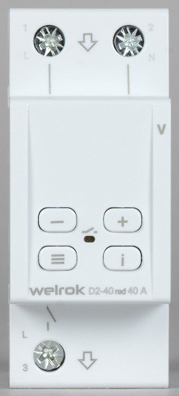
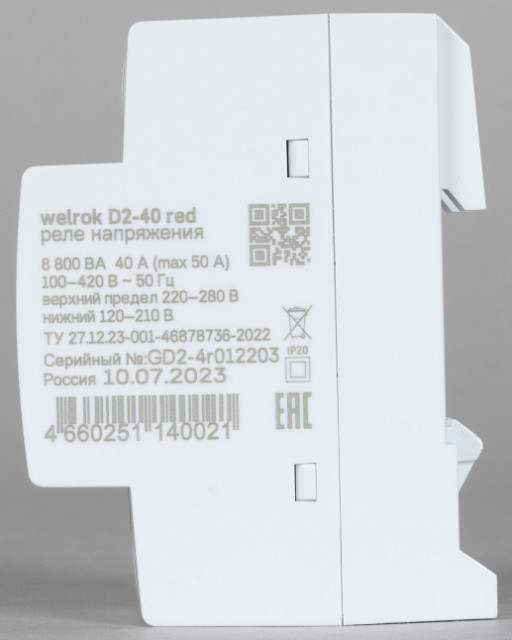
The line also includes three models for different current limits, each with the variations mentioned for VI; we received a 40-amp sample with a red indicator and no zero transit. Only voltage is controlled.
| Model | D2-40 / 40 red | D2-50 / 50 red | D2-63 / 63 red |
|---|---|---|---|
| Rated load current for category AC-1 *) , A | 40 | 50 | 63 |
| Maximum current (for no more than 10 minutes), A | 50 | 60 | 80 |
| Rated load power for category AC-1 *) , VA | 8800 | 11000 | 13900 |
*) i.e. for loads with a power factor of at least 0.95
Other parameters are the same for all models:
| Voltage limits, V | upper | 220—280 |
|---|---|---|
| lower | 120—210 | |
| Shutdown time when overvoltage, seconds | ≤0.03 | |
| Shutdown time when decreasing, seconds | >120 V | 0.1—10 |
| <120V | ≤0.03 | |
| Supply voltage, V | 100—420 | |
| Energy consumption, kWh/month | ≤0.35 *) | |
| Number of switchings | under load | ≥10000 |
| without load | ≥500000 | |
| Relay type | polarized | |
| Degree of protection | IP20 | |
| Wire cross-section for connection to terminals, mm² | ≤16 | |
| Tightening torque of terminal screws, Nm | 2.4 | |
| Operating temperatures, °C | −5… +45 | |
| Overall dimensions, mm | 85 × 36 × 66 |
*) if recalculated, the power consumption is within 0.5 watts.
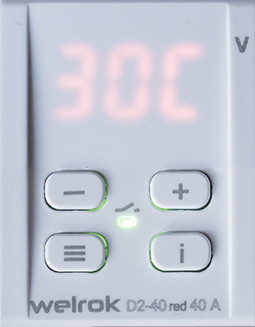
The indicator shows the voltage value, the height of the characters is 9.1 mm (0.36 inches), compare with the VI ruler:

Measurements are made using the True RMS algorithm.
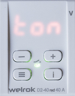
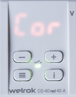

The number of available settings/settings is significantly less than the Welrok VI line. Features include a turn-on delay after an accident from 3 to 999 seconds in 3-second increments, voltage reading adjustment ±20 V, hysteresis in the range from 0 to 5 volts, options for starting the delay time, protection against frequent activation (from 1 to 5 restarts), adjusting the brightness of the indicator. There is also built-in thermal protection, a log for 100 events and a protection trip counter, as well as the ability to lock buttons.
Details are above in the description of Welrok VI-40.
General assessment of structures
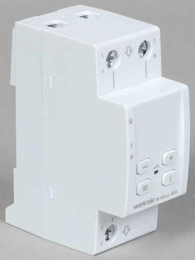
The width of both versions of the Welrok charger, like Novatek-Electro, is slightly larger than the DIN 43880 standard, but this is rather a minor difference.
The connection diagram is presented only in the product passport; it is not on the body, but this is not a problem: the relay simply opens the phase circuit. It is enough to simply connect wire L of the supply network to the upper contact of the charger, the load circuit to the lower one, and connect contact N to the neutral terminal with a wire of any cross-section. Markings are present on the terminal blocks, although the symbols may be small and not very noticeable.
The indicator in Welrok is covered with a thin plate of milky white color, which affects the readability of the symbols. When compared with samples from Novatek-Electro and Rostock-Electro, it is clear that Welrok’s readability is worse. Even at maximum brightness in a room with natural light, readings become difficult to see. Perhaps Welrok has a better situation with white indicators, but the blurring of the luminous segments is still noticeable in the pictures, which is almost absent from its competitors.


The latch is not spring-loaded, which requires a slight extension when installing the charger on a DIN rail. After this, you need to forcefully push the latch to fix it. The shank of the latch extends beyond the dimensions of the housing, making operations convenient for performing with a flat-head screwdriver without the need to insert it at a large angle.
The mounting on the rail is less reliable compared to previous samples: with moderate efforts, a slight backlash movement is possible.
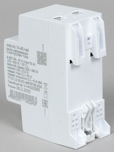
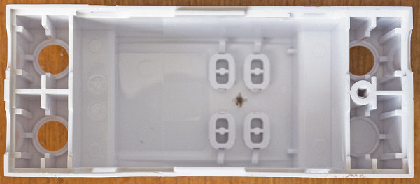
The parts of the case are connected in a combined way: there is one small self-tapping screw at the bottom (located under the latch, which must first be removed), and there are four latches on the sides.
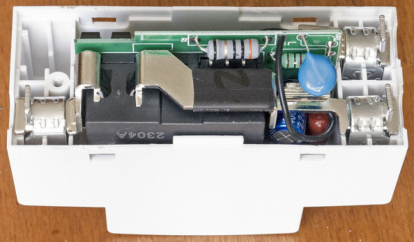
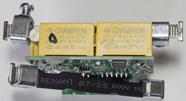
The design is also two-board, and the boards are arranged in the shape of the letter T, their connection is permanent.
In options without zero transit, there are no neutral buses: the only N terminal is welded to a thin wire that connects to the power board. The same wire is connected to the L input terminal.
The power board configuration of models VI and D2 is slightly different.
These are the only models in the review that are equipped with a 07D681K varistor to protect their own electronics, but there are no noise-suppressing X-capacitors at the input.
The control part is powered through specialized microcircuits PN8015 (PWM controller) and MC34063AC (DC-DC converter); galvanic isolation is not provided.
The type of microcontroller used on the low voltage board could not be determined due to obstruction by other components.