
The section with detailed information about processor families has all the necessary data. But let's continue to look at motherboards based on the Intel Z790. Despite the fact that this chipset is already quite old, many different options for boards based on it have appeared. Some of them are designed for the mid and high budget segment.
We are still far from a complete review of all available Z790 models, but a new wave of updated versions has already appeared, associated with the release of the 14th generation of Intel Core processors, as well as with the equipment of the boards with a new level of wireless adapters — WiFi 7.
The market for Z790 motherboards is so saturated that it sometimes seems as if motherboards based on AMD chipsets have almost disappeared. But soon interest in boards based on the Z790 will fade, and again we will return to considering boards based on AMD 6xx generation chipsets.
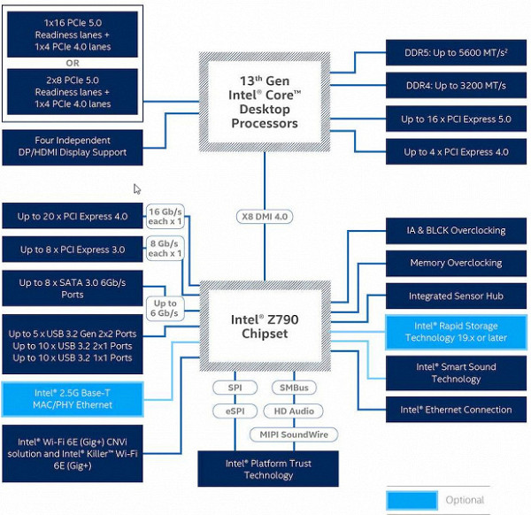
In terms of specifications, the Z790 chipset has 38 high-speed ports (High Speed In Out, HSIO). It also supports up to 5 integrated USB 3.2 Gen2x2 ports (up to 20 Gb/s each), although they require support for at least two USB 3.2 Gen2 ports, whether from the Z790 or third-party hubs.
As for the 12th, 13th and 14th generation processors, they support PCIe 5.0 with 16 lanes (used for PCIe x16/M.2 slots) and 4 PCIe 4.0 lanes hardwired to one of the M.2 slots. receiving data directly from the processor. These generations of processors can work with both DDR5 and DDR4 memory.
MSI represents three main segments of gaming motherboards: MEG, MPG and MAG. MEG are the most advanced products with powerful power systems, aimed at extreme overclocking. MPG are more affordable models with some overclocking support and without unnecessary bells and whistles. And MAG is the most affordable gaming segment with simple connections and a simple design, suitable for PCs of any configuration.
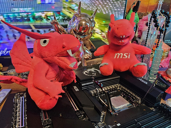
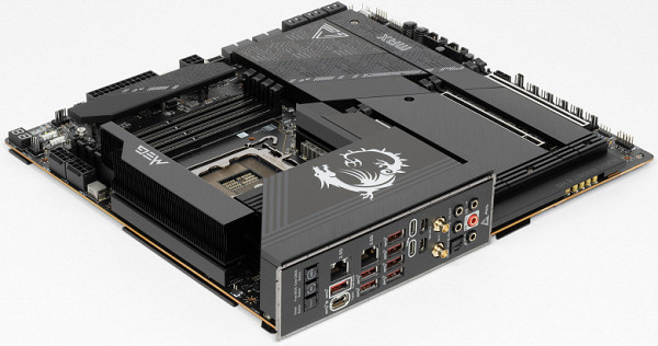
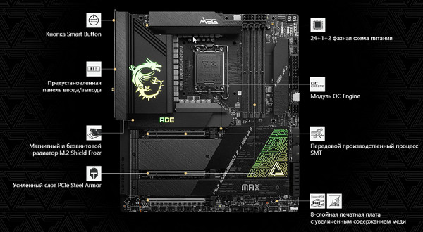
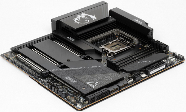
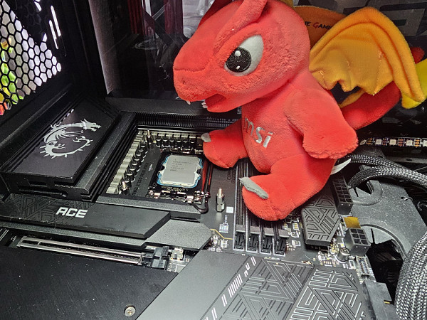
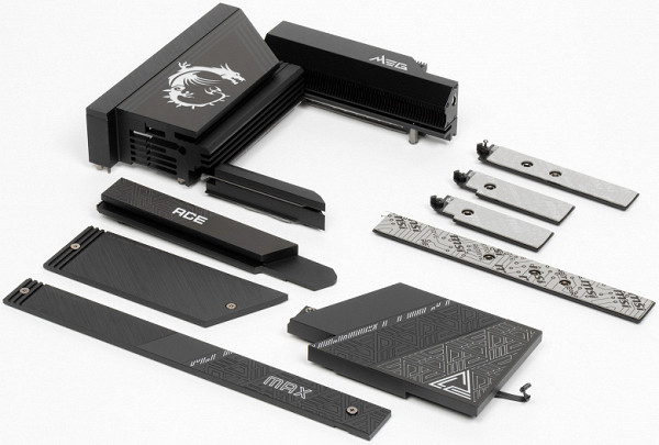
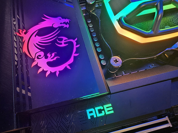
Now let's move on to the MSI MEG Z790 Ace Max motherboard. It belongs to the top MEG sub-brand, therefore it is one of the flagships of the line (and for a long time was the highest representative of the Godlike suffix).
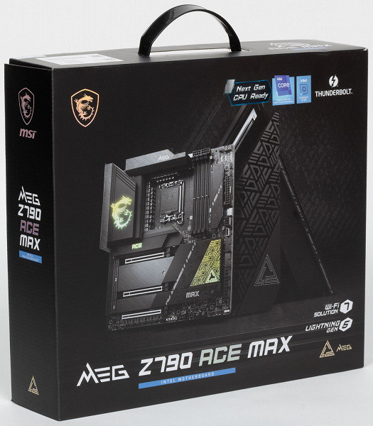
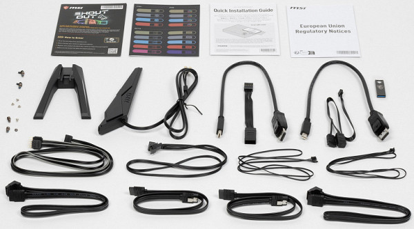
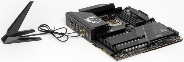
The MSI MEG Z790 Ace Max comes in a traditional black box with the signature MEG series design. The packaging corresponds to the high level of the product: in addition to standard elements such as a user manual and SATA cables, the kit also includes an antenna for the built-in Wi-Fi module, spare twist locks for M.2 slots, splitters for connecting the backlight, 2 external temperature sensors, 2 mini-DP-to-DP adapter cables, bonus stickers, a flash drive, a keychain and an adapter for convenient connection to the front panel of the case.
The software was found on the flash drive supplied with the board. However, this is unlikely to be useful: software versions are updated very often, and therefore it is recommended to download everything from the manufacturer’s website.
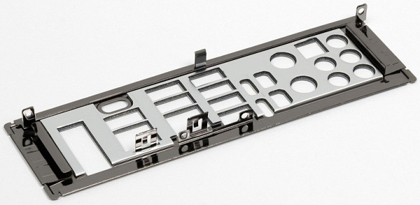
The “plug” for the rear panel with connectors is already mounted on the board itself.
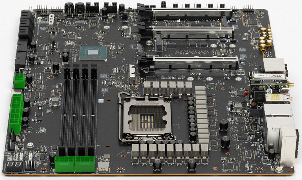
Form factor
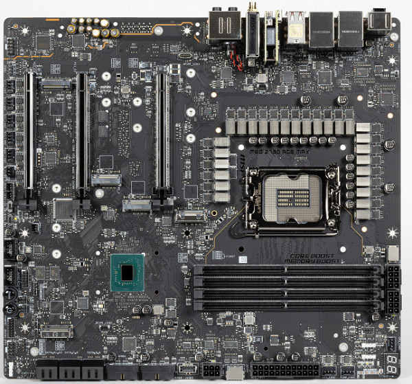
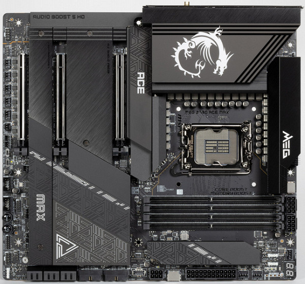
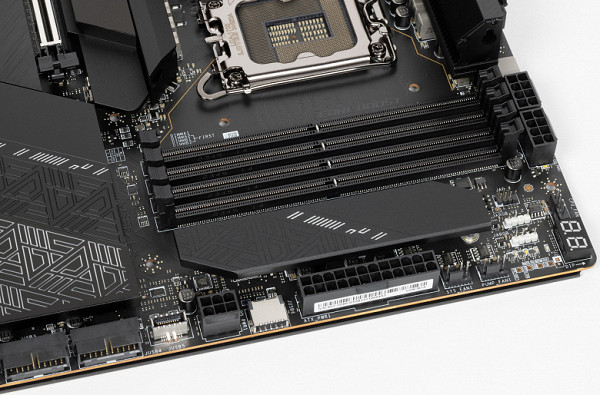
The MSI MEG Z790 Ace Max motherboard follows the E-ATX form factor and measures 305 x 277 mm. It has 9 mounting holes for installation in the case. However, it is worth noting that one of these holes is partially blocked by a heatsink for the M.2 slot.
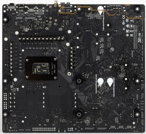
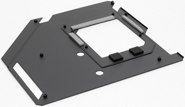
On the back of the motherboard there are several controllers and logic elements. The board is made with meticulous attention to detail, with sharp ends at solder points trimmed and the surface carefully sanded. There's also a nano-carbon coated aluminum plate on the back that helps dissipate heat and adds rigidity to the motherboard.
The commitment to quality is noticeable even in the details. However, it is important to remember that this motherboard can be difficult to install in a case that uses pressed-out raised bosses instead of the usual brass bushings to support the board.
Specifications
Traditional table with a list of functional features.
| Supported processors | Intel Core 12/13/14th generation |
|---|---|
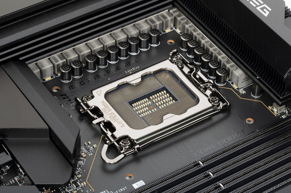
| CPU socket | LGA 1700 |
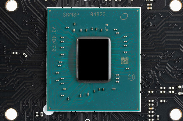
| Chipset | Intel Z790 |
| Memory | 4 × DDR5, up to 7800 MHz (XMP), up to 256 GB, two channels |
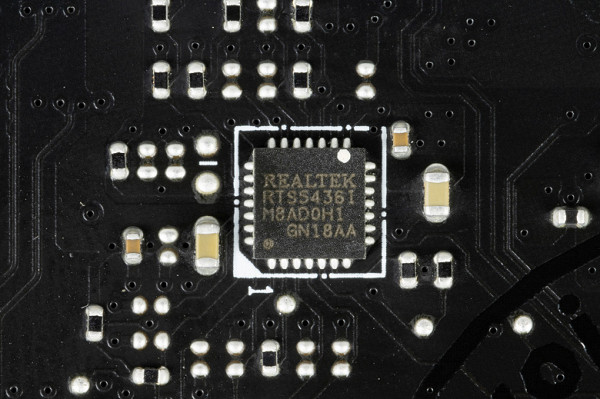
| Audio subsystem | 1 × Realtek ALC4082 (7.1) + ESS ES9280 DAC |
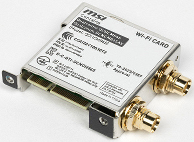
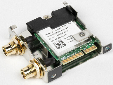
| Network controllers | 2 × Intel I225-V Ethernet 2.5 Gbps 1 × Qualcomm Dual Band Wireless QCNCM865 (Wi-Fi7 802.11a/b/g/n/ac/ax/be (2.4/5/6 GHz) + Bluetooth 5.4) |
| Thunderbolt | 1 × Intel JHL8540 Thunderbolt 4: 2 × Type-C (TB4 (40 Gb/s), USB 3.2 (20.10 Gb/s)) |
| Expansion slots | 2 × PCIe 5.0 x16 (x16+N/A, x8+x8, x8+M.2_4 modes) 1 × PCIe 4.0 x16 (x4 mode) |
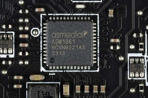
| Drive connectors | 6 × SATA 6 Gb/s (Z790+ASMedia ASM1061) 1 × M.2_1 (CPU, PCIe 4.0 x4 for 2260/2280/22110 format devices) 1 × M.2_4* (CPU, PCIe 5.0 x4 for 2280 format devices) 1 × M.2_2 (Z790, PCIe 4.0 x4 for 2260/2280 format devices) 1 × M.2_3 (Z790, PCIe 4.0 x4/SATA for 2260/2280 format devices) 1 × M.2_5** (Z790, PCIe 4.0 x4/SATA for 2260/2280/22110 format devices) |
| USB ports | 4 × USB 2.0: 2 internal 4-port headers (GL850G) 4 × USB 3.2 Gen1: 2 internal 4-port headers (GL3523) 2 × USB 3.2 Gen2x2: 2 internal Type-C headers (Z790) 1 × USB 3.2 Gen2: 1 x Type-C (Z790) 2 × USB 3.2 Gen2: 2 x Type-C (Thunderbolt4) 7 × USB 3.2 Gen2: 7 x Type-A (red) (Z790+GL3590) |
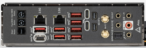
| Rear Connectors | 3 × USB 3.2 Gen2 (Type-C) 7 × USB 3.2 Gen2 (Type-A) 2 × RJ-45 5 mini-jack audio connectors 1 × S/PDIF (optical, output) 2 × DP in (Thunderbolt4) 2 antenna connectors button reset CMOS multifunction button Smart button BIOS flashing button — Flash BIOS |
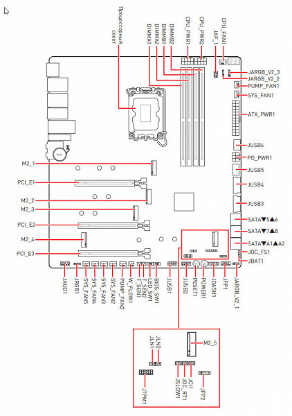
| Other internal elements | 24-pin ATX power connector 2 8-pin EPS12V power connector 1 6-pin PCIe power connector 1 M.2 (E-key) slot, occupied by wireless network adapter 1 PCIe x4 slot, occupied by Thunderbolt4 adapter 2 USB 3.2 port connectors Gen2x2 Type-C 2 connectors for connecting 4 USB 3.2 ports Gen1 2 connectors for connecting 4 USB 2.0 ports 10 connectors for connecting 4-pin fans and pumps 1 connector for connecting a non-addressable RGB strip 3 connectors for connecting an addressable ARGB strip 1 connector audio for the front panel of the case 1 switch for turning off the backlight LED_SW1 1 switch for BIOS versions BIOS_SW1 1 connector for connecting the settings panel controller JDASH1 1 connector for connecting TPM security systems 2 connectors for enabling the LN2 operating mode 1 connector for enabling the slow boot mode JSLOW1 1 connector for connecting reboot buttons JOC_RT1 1 connector for connecting safe boot mode JOC_FS1 2 connectors for a temperature sensor 1 connector for monitoring the liquid flow rate of the water pump pump W_FLOW 2 connectors for connecting control from the front panel of the case 1 power button Power 1 reset button Reset |
| Form factor | E-ATX (305×277 mm) |
| Notes | * — M.2_4 slot shares resources with PCIe slots — details below. ** — M.2_5 slot shares resources with SATA ports — details below. |
Main functionality: chipset, processor, memory
Scheme of operation of the chipset + processor combination.
Although DDR5 memory up to 5600 MHz is officially supported, modern XMP profiles can reach frequencies up to 7000 MHz and even higher. For example, the MSI MEG Z790 Ace Max motherboard supports frequencies up to 7800 MHz.
The 14/13/12th generation Intel Core processors, compatible with the LGA1700 socket and supported by the Z790 chipset, have 20 I/O lanes, including 16 PCIe 5.0 lanes and 4 PCIe 4.0 lanes. Interaction with the Z790 chipset occurs through a special DMI 4.0 x8 channel. All PCIe lines of the processor are directed to PCIe expansion slots and the M.2 port.
The Z790 chipset, in turn, supports up to 38 I/O lanes, including up to 14 USB ports (with various standards), up to 8 SATA 6Gb/s ports and up to 28 PCIe lanes (8 version 3.0 and 20 version 4.0).
The MSI MEG Z790 Ace Max board supports 12/13/14th generation Intel Core processors made for the LGA1700 socket.
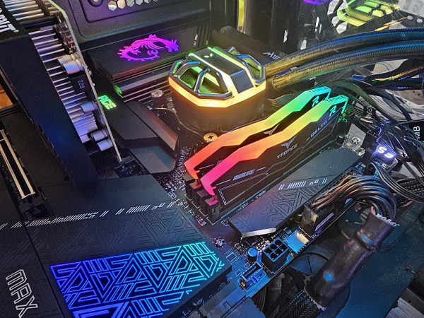
The MSI motherboard has four slots for installing memory DIMMs. To operate memory in Dual Channel mode when using two modules, it is recommended to install them in slots A2 and B2.
The board supports unbuffered DDR5 (non-ECC) memory, and the maximum memory capacity is 256 GB.
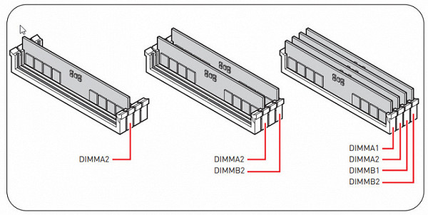
Memory module installation order
The DIMM slots do not have a metal frame, but the backplate of the motherboard itself resists any bending of the PCB when installing memory modules into the slots.
Peripheral functionality: PCIe, SATA, various “baubles”
Above, we examined the potential capabilities of the Z790+Core tandem, and now let’s see what of this and how it is implemented in this motherboard.
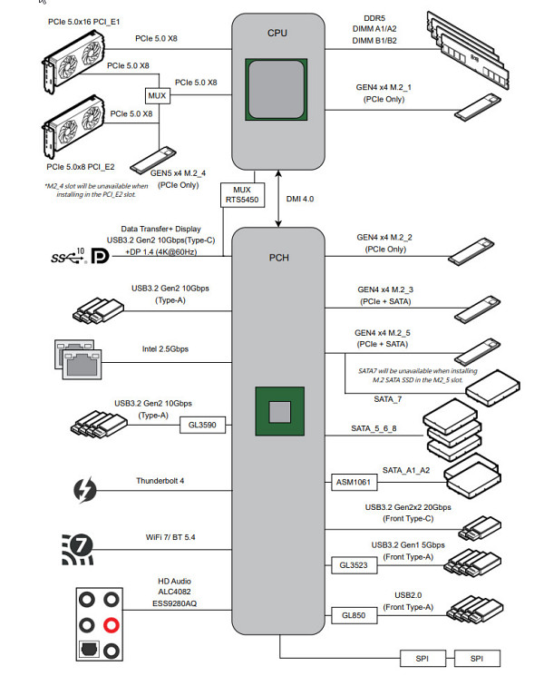
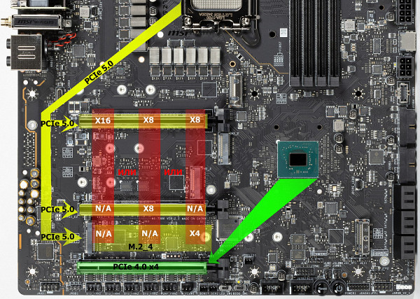
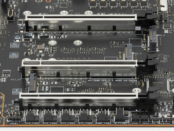
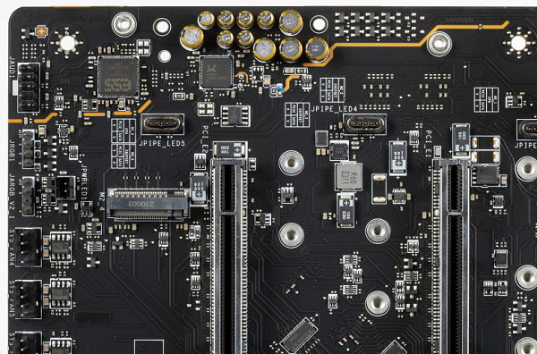
The motherboard has three slots: two PCIe x16 slots that can be used for graphics cards or other devices and are connected to the processor, and a third PCIe x16 slot that only supports 4 PCIe 4.0 lanes and is connected to the Z790 chipset.
Separately, it is worth noting that the M.2_4 slot for SSD drives is also connected to the processor, receives PCIe 5.0 signals, but shares resources with the PCIe x16_2 slot: you can use either one or the other.
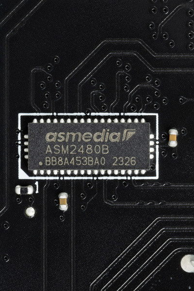
It is important to note that the motherboard has the ability to redistribute PCIe lines between slots, which is ensured by the use of Lerain Tech multiplexers.
All three PCIe x16 slots have stainless steel metal reinforcement, which increases their reliability. In addition, such protection protects the slots from electromagnetic interference.
The motherboard allows you to mount a CO of any size.
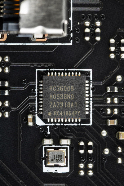
To maintain stable frequencies on the PCIe bus (and for the needs of overclockers), there is an external clock generator Renesas RG26008.
There are also PCIe 4.0 signal amplifiers (re-drivers) from ASMedia.

The PCIe 5.0 bus does not have its own amplifiers (re-drivers).
Next up are storage devices.
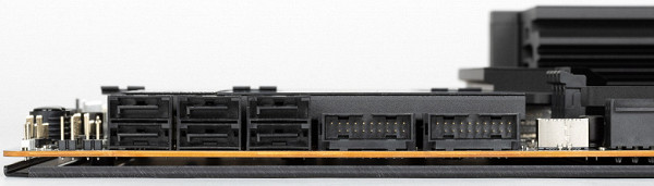
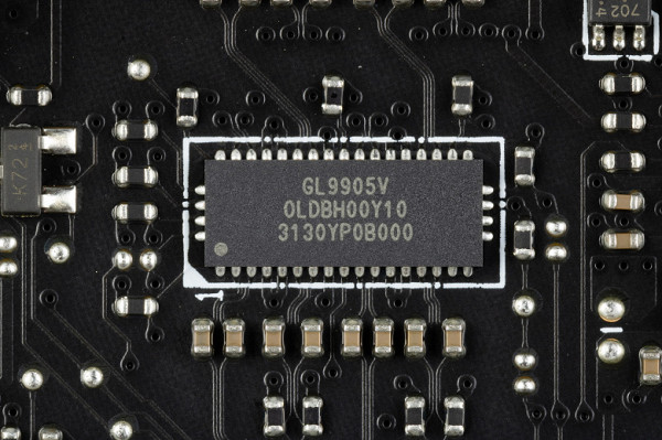
In total, the board has 6 Serial ATA 6 Gb/s connectors + 5 slots for drives in the M.2 form factor. 4 SATA ports 5,6,7,8 (strange numbering) are implemented via the Z790 chipset and support RAID creation.
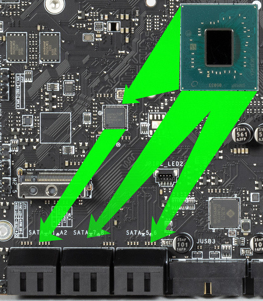
And two more SATA ports (labeled as A1, A2) are implemented through the ASM1061 hub from ASMedia (it took 1 PCIe line from the Z790), they do not support RAID.
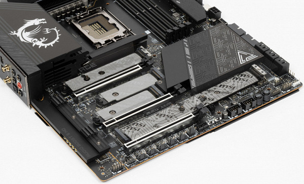
The motherboard has 5 slots of the M.2 form factor.
The M.2_2, M.2_3 and M.2_5 slots receive data from the Z790 chipset, while M.2_1 and M.2_4 receive data from the processor (M.2_1 via PCIe 4.0 and M.2_4 via PCIe 5.0).
Slots M.2_3 and M.2_5 support modules with any interface, while the remaining slots only work with PCIe interface modules.
All slots are capable of accepting modules of sizes 2260 and 2280, but slots M.2_1 and M.2_5 also support installation of modules up to size 22110. RAID can be organized on all M.2 slots.
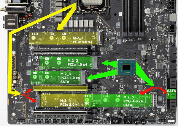
Given the extensive set of M.2 slots, it is necessary to share resources between them. The previously mentioned M.2_4 slot receives data from the processor via PCIe 5.0 and shares lanes with the PCIe x16_2 slot. Considering that the processor has only 16 PCIe 5.0 lanes, when using M.2_4 or PCIe x16_2 slots, the first video card slot will have only 8 lanes.
Also, the M.2_5 slot, connected to the Z790 chipset via PCIe 4.0 lanes, shares resources with the SATA 7 port.
To carry out all these switchings, multiplexers from ASMedia are used.
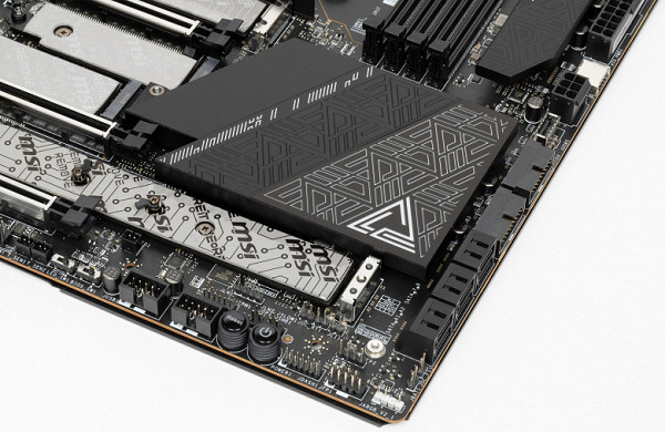
Particularly worth highlighting is the way heatsinks are secured to M.2 slots using spring locks and push-in latches that do not require the use of screws. With a simple push of the lock, the heatsink easily lifts up and out of the lock, allowing easy access to the M.2 slots.
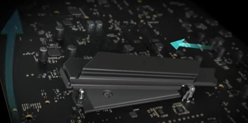
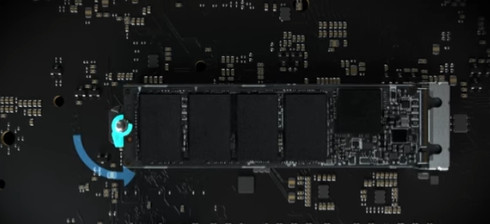
Also worth noting is the way M.2 drives are secured in the slots using twist locks mounted on the racks. This method eliminates the need for very small screws that are easy to lose.
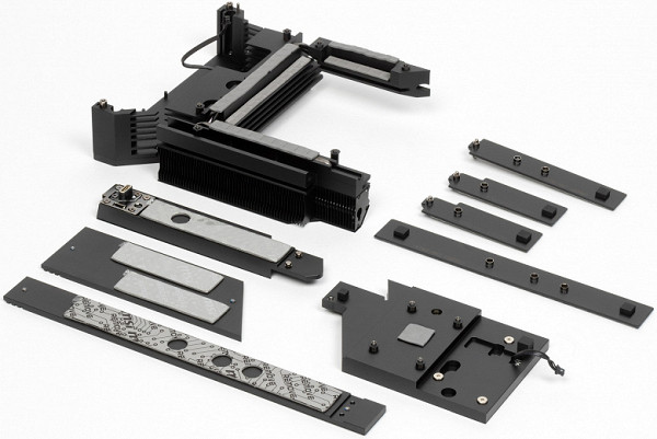
All M.2 slots have heatsinks. The top M.2_1 has a separate heatsink, while the other M.2 slots have common (paired) heatsinks.
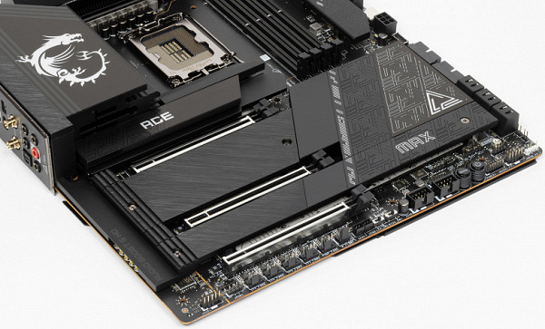
We should not forget that the lower left M.2_4 slot supports drives using the PCIe version 5.0 interface. Considering that such devices run hot these days and often come with massive heatsinks for cooling, it seems strange that MSI engineers decided to combine this slot and the adjacent M.2_5 under a single heatsink. You may even have to remove the heatsink from M.2_5 if you plan to use an M.2 PCIe 5.0 module.
Peripheral functionality: USB ports, network interfaces, I/O
Now comes USB ports and other I/O. And let's start with the back panel, where most of them are located.
To reiterate, the Z790 chipset supports a maximum of 14 USB ports, including up to 10 USB 3.2 Gen1 ports, up to 10 USB 3.2 Gen2 ports, up to 5 USB 3.2 Gen2x2 ports, and/or up to 14 USB 2.0 ports.
We also remember that there are 28 PCIe lanes, which are used to connect drives, network and other controllers (as I already explained, 27 of the 28 lines are already in use).
So what do we have? There are a total of 20 USB ports on this motherboard:
- 2 USB 3.2 Gen2x2 ports: both are implemented via the Z790 chipset and are represented by two internal Type-C ports.
(for connection to the corresponding connectors on the front panel of the case);
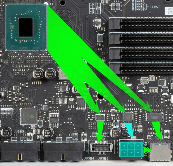
- 10 USB 3.2 Gen2 ports: 4 are implemented via the Z790 and are represented by: 3 — on the rear panel with Type-A ports (red); 1 — on the rear panel with a Type-C port; 2 more are implemented via Thunderbolt 4 and are also presented on the rear panel with Type-C ports; and 4 are implemented via the Genesys Logic GL3590 controller
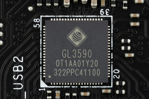
(it uses 1 USB 2.0 line from the Z790) and is represented by 4 Type-A ports (red);
- 4 USB 3.2 Gen1 ports: all implemented via Genesys Logic GL3523 controller
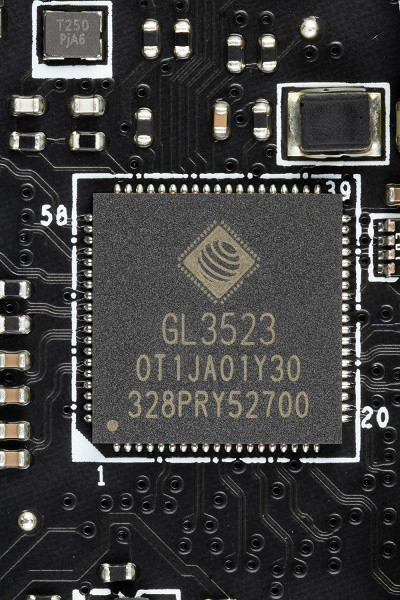
(it uses 1 USB 2.0 line from the Z790) and is represented by 2 internal connectors
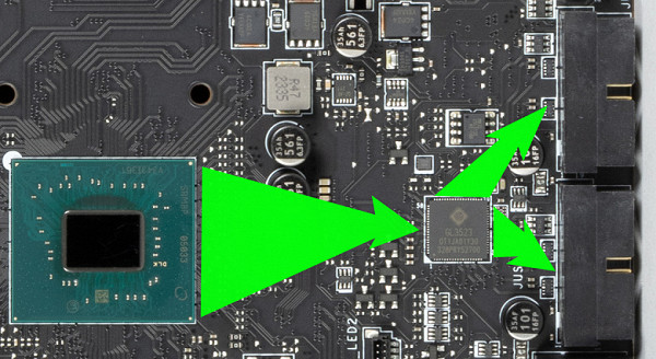
on the motherboard (each with 2 ports);
- 4 USB 2.0/1.1 ports: all implemented via Genesys Logic GL850 controller
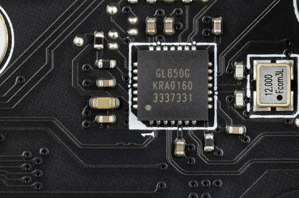
(it uses 1 USB 2.0 line from the Z790) and is represented by two internal connectors
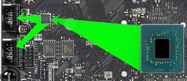
It's important to note that to achieve very fast charging of up to 60W on a USB 3.2 Gen2x2 port, you must be sure to connect power to the 6-pin PCIe connector located next to the internal Type-C ports. This controller is controlled by Realtek.
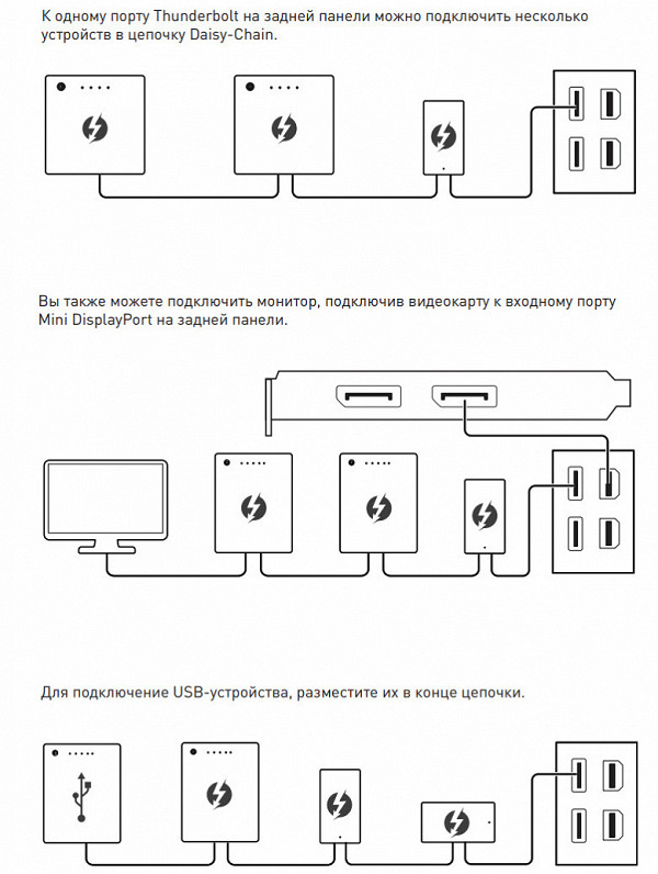
The board also features Intel Thunderbolt 4, provided by the Intel JHL8540 controller. This controller is a separate module that fits into a dedicated PCIe x4 4.0 slot located in the rear I/O port area.
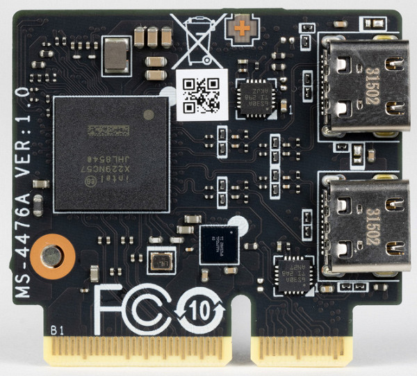
The module has 2 Type-C connectors designed for data transfer via the Thunderbolt protocol, as well as for use as USB 3.2 Gen2/1 ports. In addition, the module is equipped with two mini-DP connectors for receiving signals from external sources such as video cards. The delivery set includes adapters from full-size DP connectors to mini-format.
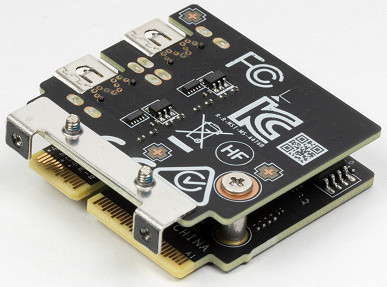
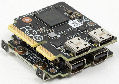
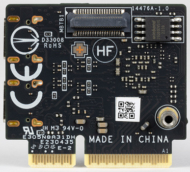
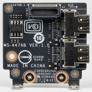
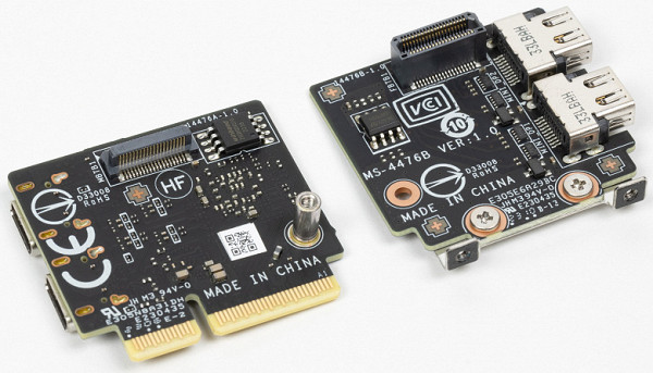
The module is made in the form of two PCBs connected to each other via an adapter.
That is, through TB4 we can connect monitors and other receivers with a Type-C interface with ultra-high-resolution image output.
Now about networking matters.
The motherboard is equipped with excellent communication capabilities! There are two high-speed Intel I226-V Ethernet controllers capable of operating according to the 2.5 Gbit/s standard.
The motherboard also features a comprehensive wireless adapter based on the Qualcomm QCNCM865 controller. This adapter provides support for Wi-Fi 7 (802.11a/b/g/n/ac/ax/be) at 2.4/5/6 GHz frequencies, as well as Bluetooth 5.4. Installed in the M.2 (E-key) slot, it has connectors for attaching external antennas, which are located on the rear panel.
The plug, traditionally placed on the back panel, in this case is already put on and is shielded from the inside to reduce electromagnetic interference.
Audio subsystem
The motherboard also features a comprehensive wireless adapter based on the Qualcomm QCNCM865 controller. This adapter provides support for Wi-Fi 7 (802.11a/b/g/n/ac/ax/be) at 2.4/5/6 GHz frequencies, as well as Bluetooth 5.4. Installed in the M.2 (E-key) slot, it has connectors for attaching external antennas, which are located on the rear panel.
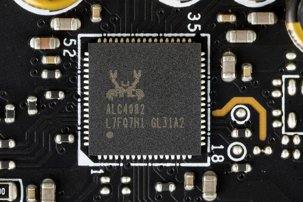
The path uses an ESS Sabre9280 DAC and an oscillator to ensure accurate DAC operation.
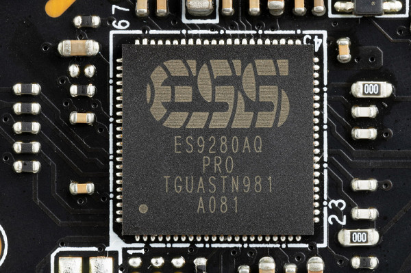
There is no operational amplifier.
The audio circuits of the board use “audiophile” Nichicon Fine Gold capacitors.
The audio path is located on the corner part of the board and does not intersect with other elements. All audio jacks on the rear panel are gold plated.
Power, cooling
There are 4 connectors to provide power to the board. In addition to the standard 24-pin ATX connector located on the right side of the board (on the left in the photo), there are also two 8-pin EPS12V connectors and one 6-pin PCIe connector. The latter is used to support USB 3.2 Gen2x2 port power, allowing mobile devices to be quickly charged at up to 60W.
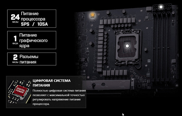
The processor power supply circuit is made according to the 24+2+1 scheme: a total of 27 phases, 24 on VCore, 2 on VCCIO and 1 on the integrated graphics core.
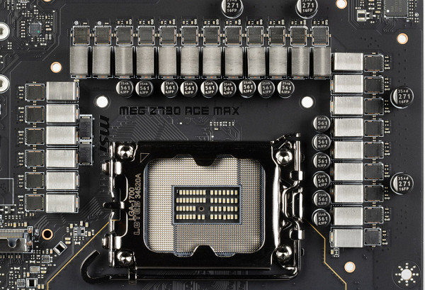
Each VCore phase channel has a superferrite choke and a Renesas RAA 22010540 MOSFET) rated at 105 A.
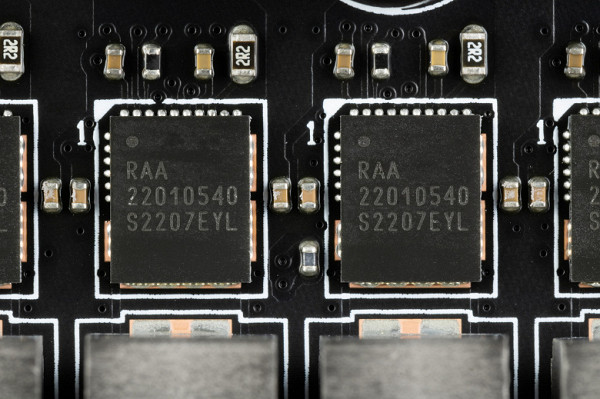
Each VCore phase channel has a superferrite choke and a Renesas RAA 22010540 MOSFET) rated at 105 A.
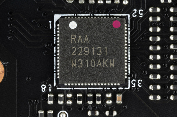
The board does not have power phase doublers, so it is clear that the 24 VCore power phases are controlled in parallel. In fact, the PWM controller controls 12 VCore phases.
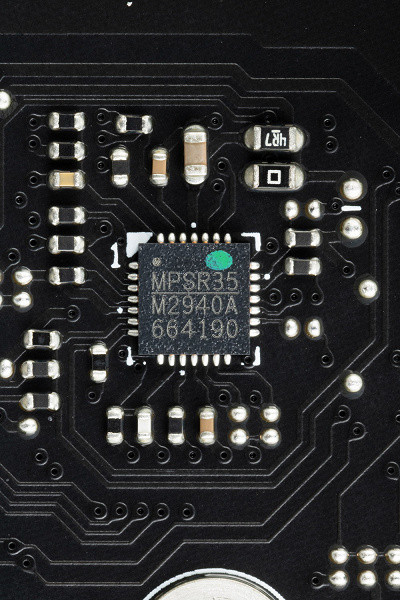
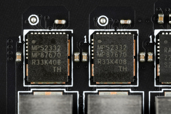
The VCCIO unit has its own two-phase power circuit, controlled by the MP2940A PWM controller from Monolithic Power Systems, as well as MP87670 assemblies (up to 70 A) from the same manufacturer.
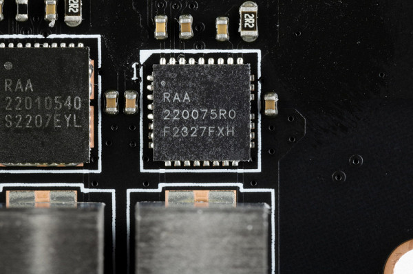
The iGPU power subsystem has a superferrite choke and a RAA 220075R0 MOSFET from Renesas) at 75 A. Thus, the above-mentioned PWM controller RAA229131 from Renesas actually controls 13 phases.
Now about cooling.
All potentially very hot elements have their own heat sinks.
The radiator for cooling the chipset is installed separately from the radiators of the power converters. The VRM section is equipped with three radiators connected by a single heat pipe and located at right angles.
The VRM heatsink running along the rear block of ports has a casing that covers the same block equipped with backlighting.
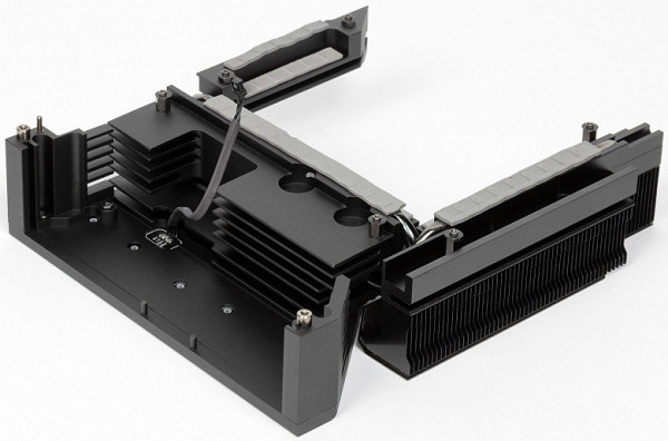
As mentioned earlier, each M.2 slot has its own heatsink on the top, with the exception of the top slot, which has an individual heatsink. All M.2 slots are equipped with thermal pads on both the top and bottom heatsinks, ensuring efficient cooling. In addition, the motherboard has a backplate on the reverse side, which also helps cool the VRM thanks to the use of thermal pads.
Backlight
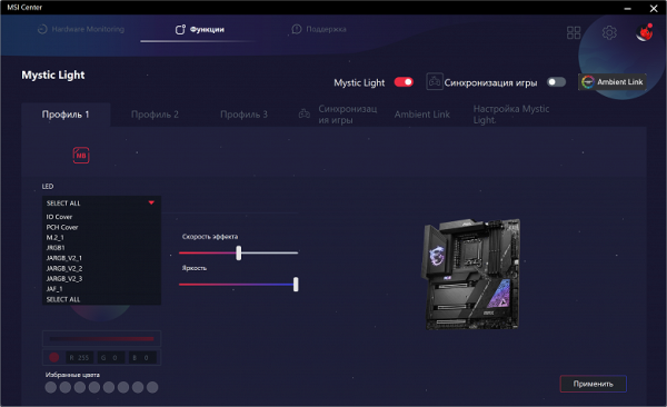
Top MSI motherboards always attract attention with their beautiful lighting and original design. In this model, special lighting effects are created on the casing above the rear port block, and the Ace logo on the M.2_1 heatsink is also illuminated. In addition, the board has 4 connectors for connecting external lighting, controlled through the Mystic Light program, available as part of MSI Center.
Of course, if anyone doesn’t like this beauty, you can always turn off the backlight through the software.
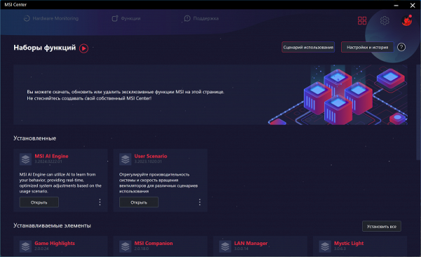
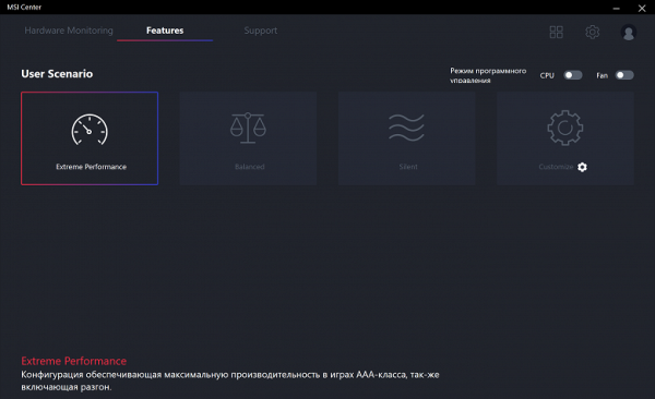
Windows software
All necessary software is available for download on the manufacturer's official website MSI.com. Basically, this is a single global program — MSI Center. All other utilities are included in it.
Let's start with the Mystic Light lighting control section. This utility provides as many as 25 (!) lighting options for elements of the board's LED lighting system (three ARGB connectors + an RGB connector). You can select the glow mode for both individual elements and the entire group as a whole. In addition, the utility automatically detects the presence of video cards from MSI and memory modules from a number of well-known manufacturers.
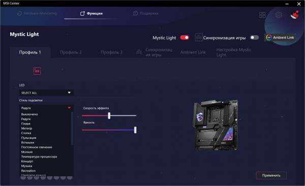
The backlight can be synchronized (though then there will be fewer options).
MSI Center also monitors the operation of main units as a whole.
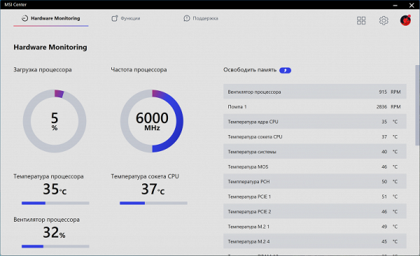
You can activate monitoring as a separate window, which can be switched if the number of items marked for monitoring does not fit in the window. This window can be placed in a convenient location, such as on the side, to easily monitor the status of the system during overclocking or intense gaming workload. However, in this case you will have to abandon the “full screen” mode in the game.
MSI Center offers two themes: light and dark.
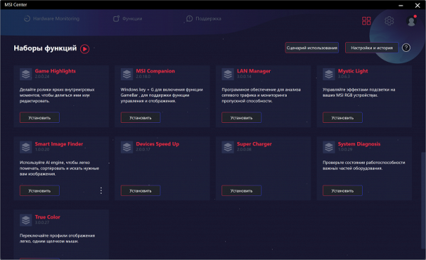
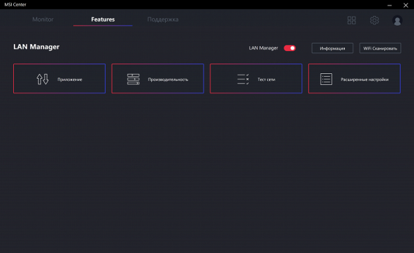
In addition to backlight control and monitoring, this program has many other built-in utilities.
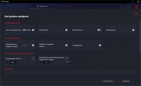
For automatic overclocking without entering the BIOS, there is a tab with preset settings for frequencies and voltages.
A tab for managing network connections is also available: the application allows you to configure the priority of accessing network connections for specific applications. This is useful for optimizing data transfer speeds, especially in games and other similar scenarios.
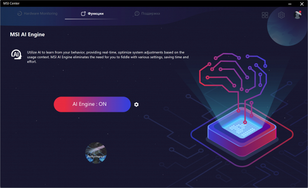
AI is present here too. While specific details are not revealed, it is mentioned that a PC with this motherboard can optimize its performance by analyzing previous usage. So far, the testing process has not revealed any concrete results from the work of the AI. It is likely that several days or weeks of active PC use will be required to form any statistical base for a neural network.
We should also note the proprietary sound control panel from Nahimic, which accompanies the current Realtek audio driver.
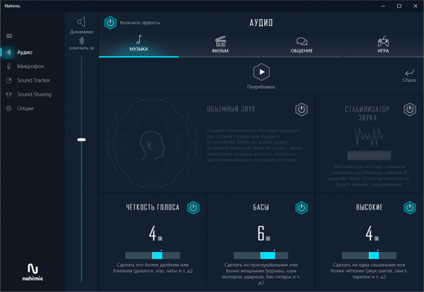
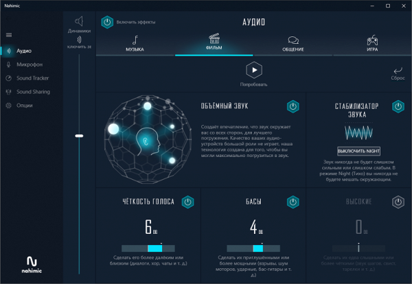
Actually, you can customize the sound “to suit you” both in games and simply when listening to music. The settings are especially interesting
BIOS Settings
All modern motherboards are equipped with UEFI (Unified Extensible Firmware Interface), which is essentially a miniature operating system. To enter settings when the PC boots, you still need to press the Del or F2 key.
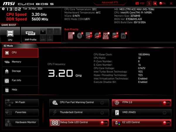
We find ourselves in the general “simple” menu, where essentially there is only one information, so we press F7 and we find ourselves in the “advanced” menu.
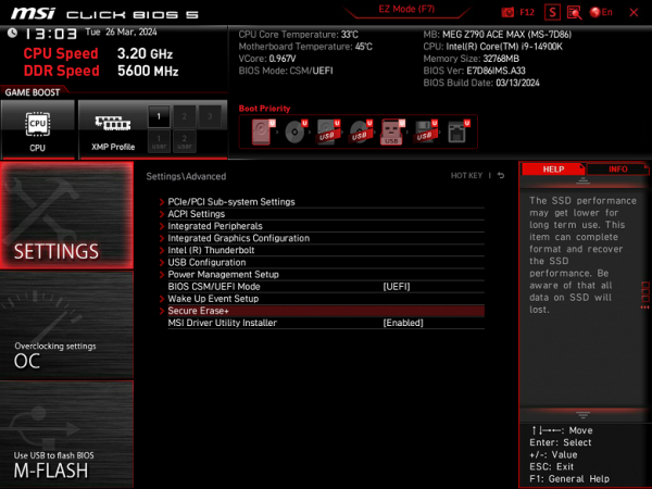
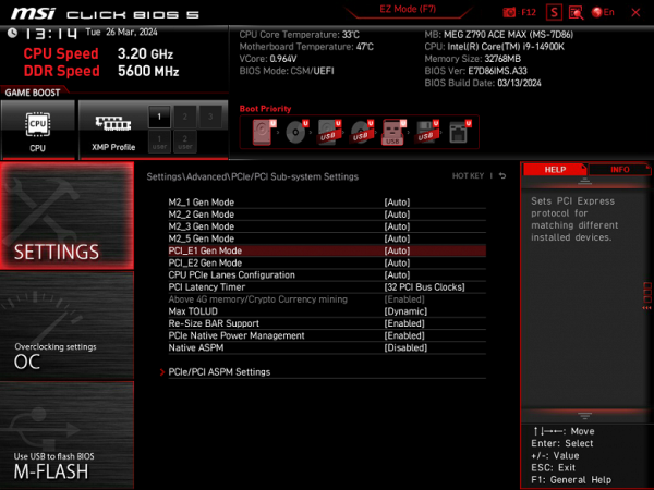
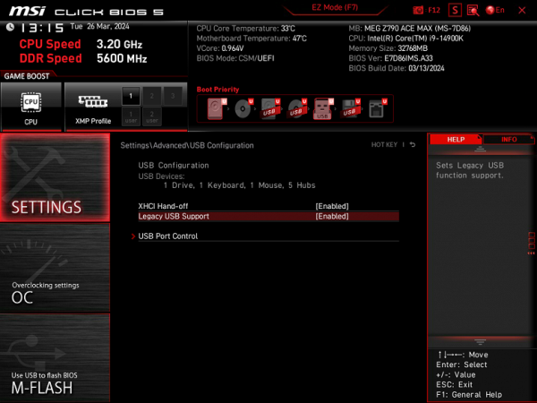
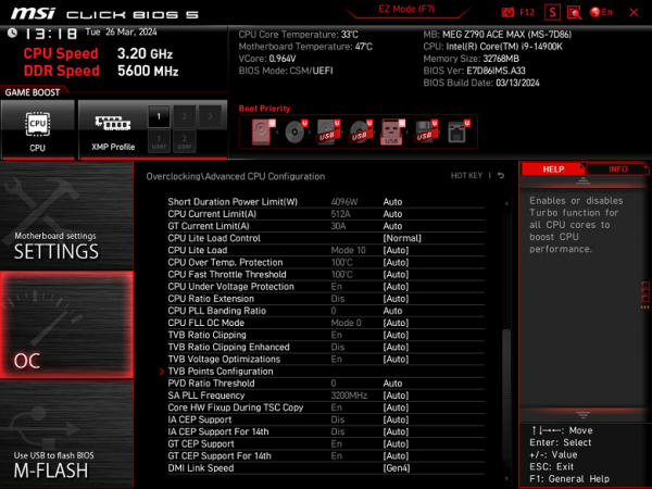
Peripheral management. There are many interesting positions where you can control each USB port. How to change the operating modes of PCIe and M.2 slots.
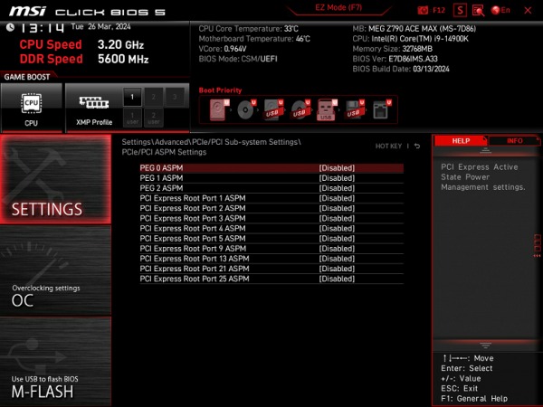
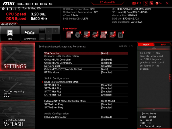
You should pay special attention to the section for managing M.2 and PCIe slots. As a reminder, both PCIe slots are connected to the processor, and two M.2 slots (M.2_1 and M.2_4) are connected to the CPU. Moreover, M.2_4 shares resources with PCIe x16_2, so you need to set the necessary options in the settings. In addition, M.2_5 shares resources with the SATA port, which also requires attention during configuration.
Also, do not forget about the Smart Button settings, which is located on the back panel of the motherboard. Its modes are also set in the BIOS.
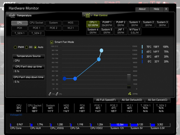
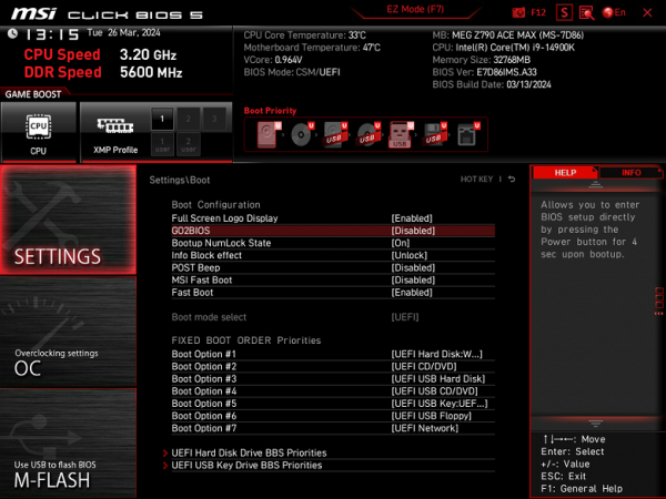
Monitoring and boot menu options are well known to everyone. There is also a utility for configuring the fan sockets.
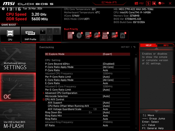
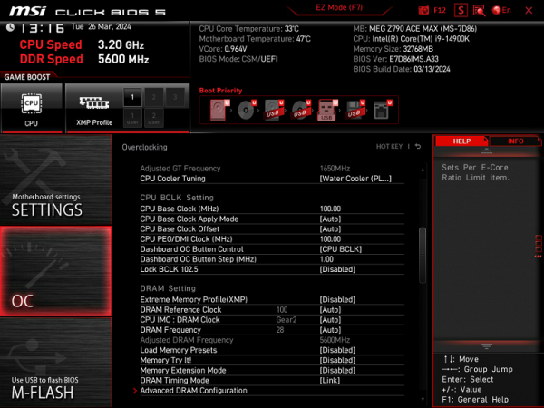
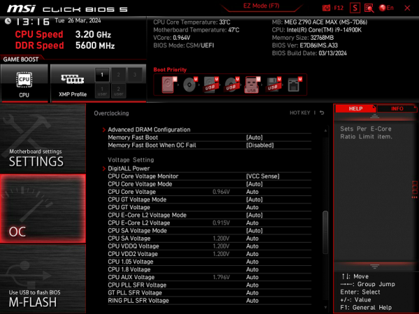
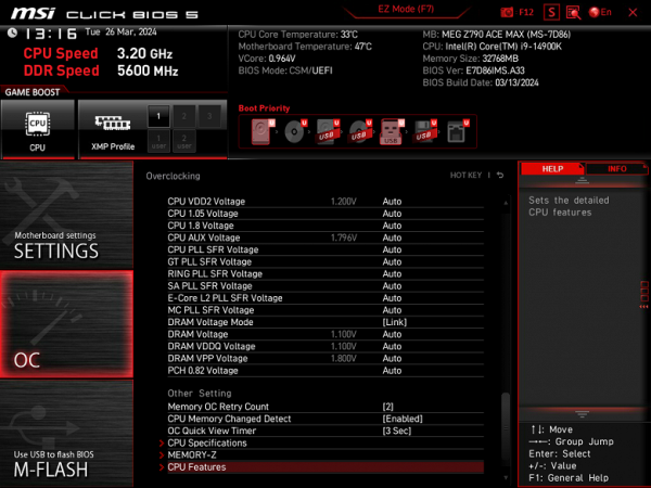
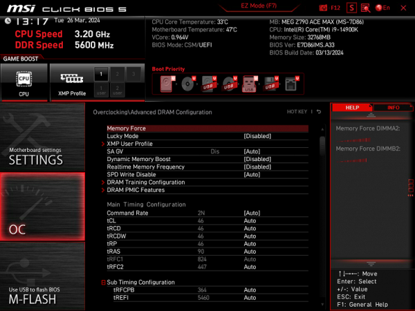
For overclocking, there are essentially standard options within the framework of what Core processors and DDR5 RAM support. We remember that there is an external clock generator, so you can flexibly change the frequency of the base bus.
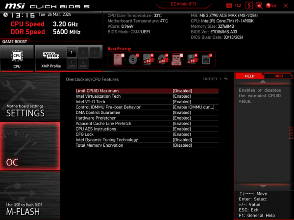
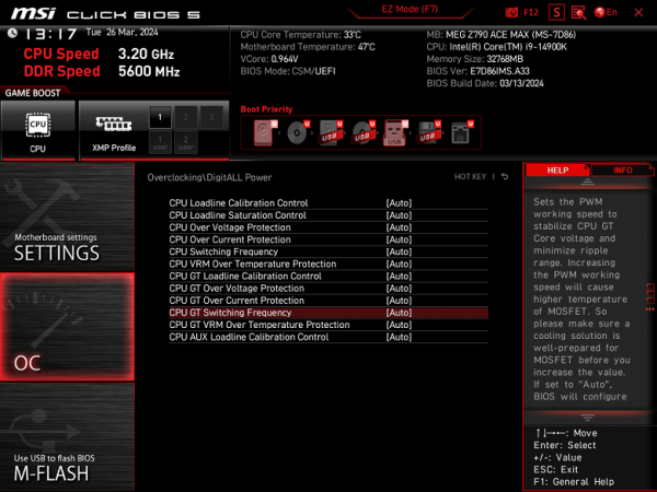
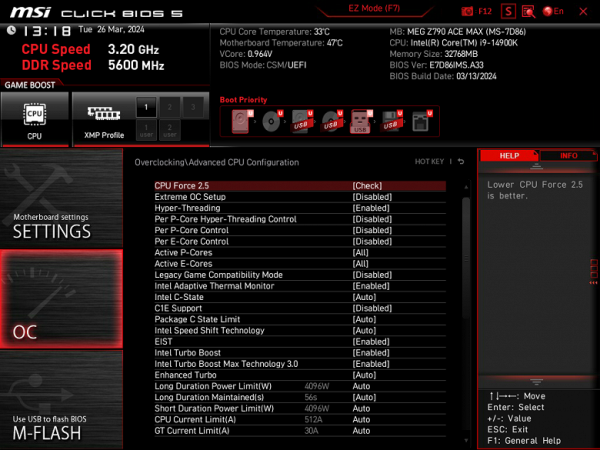
There are too many options, as it should be in the MEG line, although for modern top-end processors the lion's share is probably useless, because the processor itself already operates at greatly increased frequencies (using Intel TurboBoost, etc.).

For those who prefer to disable auto-overclocking (TurboBoost) of the processor and operate only at the minimum standard frequency for the sake of quiet operation of the cooling system, many options are provided. Some may be hampered by SpeedShift technology, which tends to lower core frequencies when the CPU is not actively used to save power. Particularly noteworthy is the Multi-Core Enhancement (MCE) technology, which removes any restrictions on power consumption, allowing CPU frequencies to rise as much as possible until the heating limit is reached. By default, it is set to Auto (using BIOS settings), which leads to differences in maximum frequencies in the absence of synchronization across all cores. Those who want to stay within the specified TDP limits should disable MCE.
Performance (and overclocking)
Full test system configuration :
- MSI MEG Z790 Ace Max motherboard;
- Intel Core i9-14900K processor 4.5-5.8 GHz;
- RAM TeamGroup T-Force Delta RGB 32 GB (2×16) DDR5 (CL36-46-46-84) (XMP 7600 MHz);
- SSD TeamGroup MP44L NVMe PCIe 4.0 1 TB;
- Palit GeForce RTX 3050 StormX video card ;
- power supply Super Flower Leadex Platinum 2000W (2000 W);
- LSS Sapphire Nitro+ S360-A AIO CPU Cooler ;
- TV LG 55Nano956 (55″ 8K HDR);
- Asus ROG Strix Scope keyboard and Logitech mouse.
Software:
- operating system Windows 11 Pro, 64-bit
- AIDA 64 Extreme
- 3DMark Time Spy CPU benchmark
- 3DMark Fire Strike Physics benchmark
- 3DMark Night Raid CPU benchmark
- HWInfo64
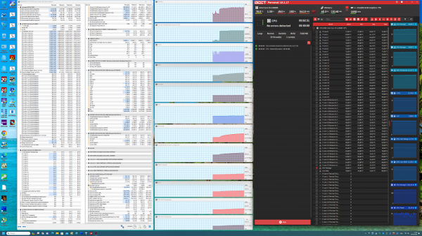
- OCCT v.12.1.16
- Adobe Premiere CS 2019
We launch everything in default mode (but at the same time activate MCE). Then we load it with tests.
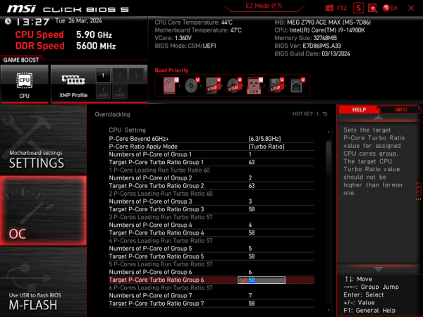
In auto-overclocking mode, we got 5.7 GHz for all P-cores and 4.4 GHz for all E-cores! Let me remind you that P-cores are productive cores with two threads each, and E-cores are energy-efficient, with one thread per core.
This auto-overclocking has become standard for the Core i9 14900K on top-end motherboards with the Z790 chipset that have a powerful power supply. All system parameters for heating components remained normal, but it is worth noting that CPU consumption exceeded 260 W.
The BIOS settings of this board contain a huge number of overclocking options, it would take weeks to test even some of them. Among the options there was a setting with the ability to set 6.3 GHz on some cores (this is a preset configured by MSI specialists). However, this setting did not work: the OCCT test program refused to start, and after a minute the system generated a BSOD.
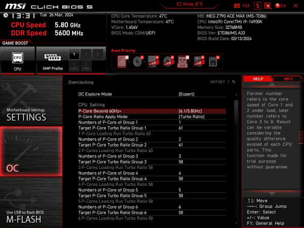
Reduced to 6.1 GHz. In this case, the system was already working stably.