The EKF brand offers a wide range of equipment for input, distribution and metering of electricity, automation of technological processes, including the development of integrated energy-efficient solutions. These products are supplied to 20 countries around the world.
The range also includes a number of E-Power uninterruptible power supplies, including single-phase line-interactive and double-conversion, as well as three-phase models and DC UPS, less common among mass users.
The E-Power PSW600 series includes line-interactive sources with pure sine wave in battery mode, suitable for powering gas boilers and heating system pumps, security and fire systems, telecommunications equipment and servers, medical equipment.
We will consider a model with an output power of 2000 VA / 1600 W, designed for rack mounting, but also suitable for floor or table installation. The series includes similar UPS units with power ratings from 1000 to 3000 VA, as well as models in enclosures designed exclusively for floor-standing or desktop use, including a model with a power rating of 500 VA / 400 W.
Description, parameters, equipment
The E-Power PSW600 UPS clearly states:
- Output voltage in the form of a pure sine wave when operating from battery power.
- Availability of AVR (Auto Voltage Regulation).
Protection of the computer/telephone line is implied by the presence of the corresponding connectors, and the cold start option is described in the instructions. Support for the Smart Battery standard and the presence of protection against impulse interference in the power supply network are not mentioned.
The declared characteristics, taken from the user manual and from the manufacturer's website, are presented in the table. However, in the instructions, the indexes of the PSW600 series models differ from those indicated on the official website: they include an indication of the output power in volt-amperes — the 500 VA UPS is designated as PSW605, the 3000 VA UPS is designated as PSW630, and our device is PSW620, respectively. The same designation is contained on the sticker on the case, with additional letters RTB: the first two mean the design in a case that allows for both rack mounting and separate placement, the last one means built-in batteries.
| EKF E-Power PSW620-RTB | |
|---|---|
| Input voltage range (stabilization mode) | for U out =200 V: 145—260 V for U out =220 V: 165—280 V for U out =230 V: 175—290 V for U out =240 V: 185—300 V |
| Input voltage frequency | 50/60 Hz ±5% |
| output power | 2000 VA / 1600 W |
| Output voltage (when operating on battery, adjustable) | 200/220/230/240V |
| Automatic Voltage Regulation (AVR) | There is |
| Output voltage stability | ±5% |
| Output voltage frequency (when operating on battery, adjustable) | 50/60 Hz ±0.3 Hz |
| Output waveform when running on battery power | sine wave |
| Nonlinear distortion coefficient | ≤ 5% |
| Output power factor (cos φ) | 0.8 |
| Efficiency: inverter/total | 85% / 93% |
| Switching time | ≤ 10 ms |
| Battery type, voltage and capacity | lead-acid maintenance-free 3 x 12 V, 9 Ah |
| Maximum charging current of the built-in battery (configurable) | 1 / 2 / 3 A |
| Typical charging time of the built-in battery | n/a |
| Possibility of connecting an additional battery | No |
| Battery life at full load | 2 minutes |
| Output connectors | 6×C13 (IEC 60320), all battery powered |
| Interface | USB-B |
| Sound alarm | There is |
| Data Line Protection | yes, 8P8C (RJ-45) |
| Function of starting equipment without connection to the power grid (cold start) | There is |
| Protection | from overload and short circuit, overheating, overcharging and deep discharge of the battery |
| Filtering impulse noise | there is (we found out) |
| Overload capacity | when operating from the mains: 110% — 120 sec, 125% — 60 sec, 150% — 10 sec, then switch to bypass when operating from the battery: 110% — 120 sec, 125% — 10 sec, 150% — 5 sec, then switch off |
| Dimensions (W×D×H) | 132×410×440 mm |
| Height at stand | 3U |
| Net/gross weight | 21.3 / 24.5 kg |
| Noise (at a distance of 1m) | n/a |
| Working conditions | humidity up to 93% temperature from +5 to +40 °C |
| Standard Warranty | UPS: 3 years (up to 42 months from date of manufacture) Battery: 1 year (up to 18 months from date of manufacture) |
| Life time | at least 5 years |
The UPS is supplied in a box made of ordinary cardboard.

In addition to the UPS itself, the kit includes a set of brackets for rack mounting (including the corresponding screws and anchors), supports for vertical placement, cables for connection to an external AC network and a USB interface, a CD with software and instructions in Russian.
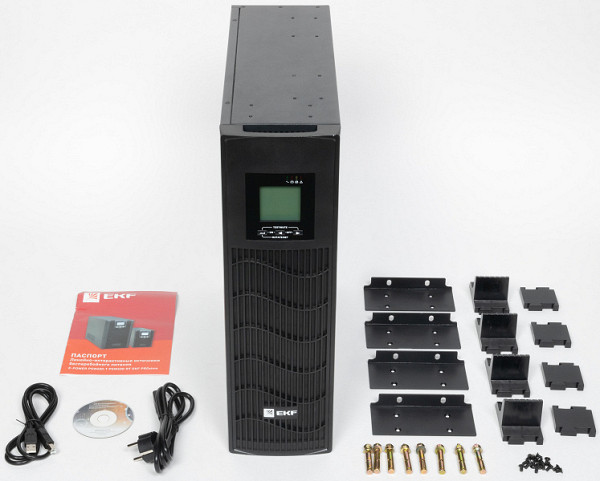
Of the options, official sources mention adapters — SNMP and «dry contacts», but not in connection with the E-Power PSW600 series models.
Appearance and controls
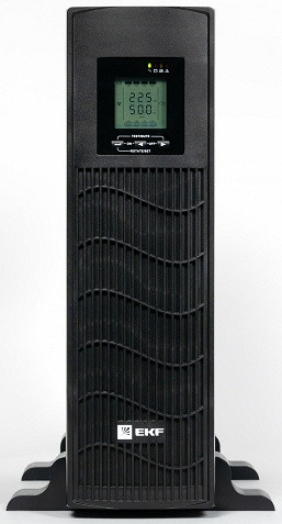
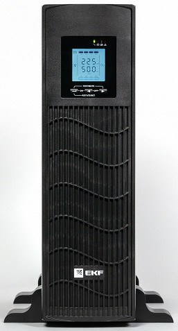
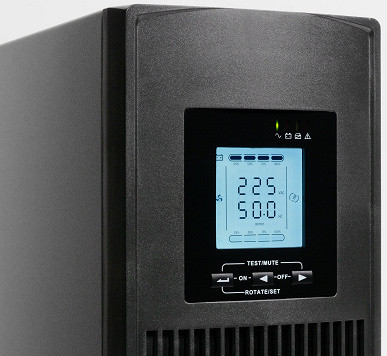
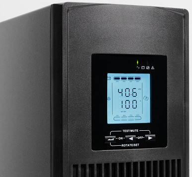
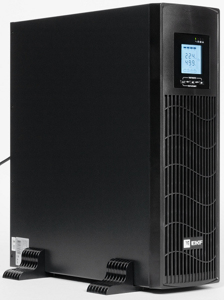
The case is metal, black. The front panel is plastic. The control panel is located in the upper part (with vertical installation of the UPS, unless otherwise specified), and almost the entire remaining surface is occupied by a grill through which air is supplied for cooling.
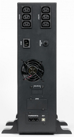
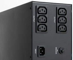
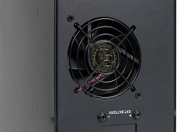
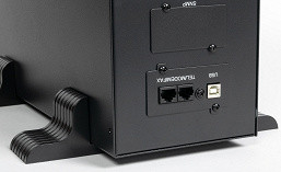
The rear panel features two groups of three C13 (IEC 60320) output sockets, which are connected in parallel and powered by the battery. There is also a C14 input socket, a fuse holder, a ventilation hole with a metal mesh, plugged openings for the SNMP adapter and contacts for the external battery (available in other models), a pair of 8P8C (RJ-45) connectors for protecting communication lines, and a USB-A port for communication with a computer.
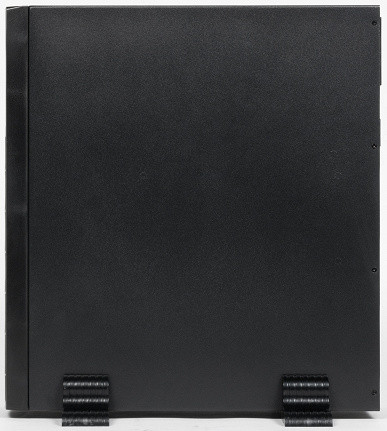
The narrow ends have threaded holes for attaching brackets when mounting in a rack.
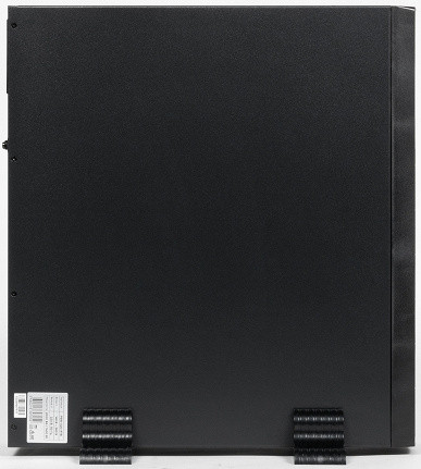
On the back of the left side surface there is a sticker with information, including the serial number.
There are only three buttons on the control panel, the use of which requires different durations of pressing or certain combinations. The UPS is turned on by pressing the middle and left buttons simultaneously, and turned off by pressing the middle and right buttons. However, «turning off» in this case is specific: there is no complete shutdown of the outputs, a transition to the bypass mode occurs, in which the input voltage is directly supplied to the output sockets, bypassing the inverter and the AVR system. Thus, voltage on the loads will always be present if the UPS is connected to the network, which is important to consider from a safety point of view.
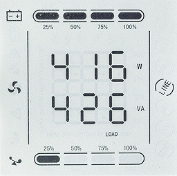
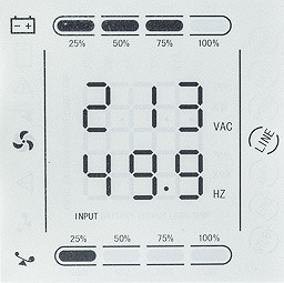
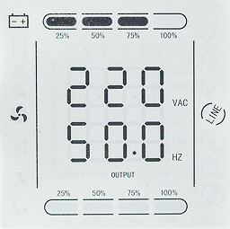
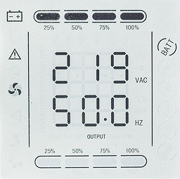
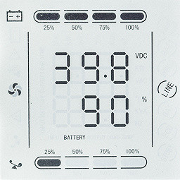
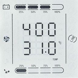
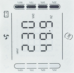
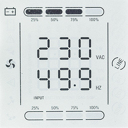
The LCD display with a diagonal of 6.3 cm (according to our measurements) is monochrome, with dark characters on a light background. The horizontal and vertical viewing angles are quite good, but when viewing from slightly above (a deviation of 20-25 degrees from the normal is enough), almost nothing is visible on the screen. This can be very inconvenient when placing the UPS on the floor.
The backlight turns on when you press any button and turns off automatically after a minute (this cannot be changed in the settings menu). Its brightness is rather excessive and cannot be adjusted, and the contrast is clearly insufficient: unused symbols and segments of digital characters are visible from many viewing angles, which makes it difficult to perceive the information.
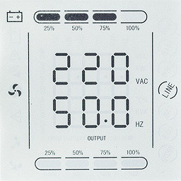
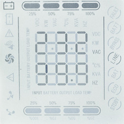
The display shows a large amount of information, but the description and illustrations in the instructions do not always correspond to the actual readings of our model. On the screen you can see:
- two groups (one above the other) of three large digits — voltage and frequency at the input and output, load power in watts and volt-amperes, temperature inside the case (plus another parameter, always equal to 400), battery voltage and percentage of charge remaining;
- to the right of these numbers are the designations of the quantities they display: W (watts), V (volts with specification of VAC and VDC), HZ (hertz), % (percent), etc.;
- under the numbers — what they refer to: Input, Output, Load, etc.;
- diagrams with 4 segments each — load and battery charge levels;
- on the left and right are symbols displaying modes and states: operation from the network (in linear or bypass mode) or battery, overload, battery failure, emergency, and others;
- a fault code or warning code can also be displayed, the decoding of which is provided in the instructions.
The displayed parameters are selected using the buttons with triangular arrows (middle and right), and the choice is remembered, which is convenient for long-term observation of certain values - however, this is hampered by the automatic shutdown of the screen backlight.
There are four LED indicators above the display. The green left one shows the UPS is on (when operating from the network or battery), the next red one — battery operation, the third (yellow) — bypass or setup mode, and the right (red) indicates a problem, including the absence of an external network.
To rotate the image to the position corresponding to the UPS placement (vertical or horizontal), you must press the left button twice within 0.5 seconds. In this case, the contents of the digital character cells and some symbols are rotated by 90 °, and the digitization of the diagrams is rotated by 180 °.
Setting up UPS parameters
We demonstrate them not to retell the instructions, but to show the capabilities of the source and voice questions that arose during the study.
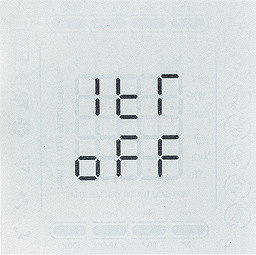
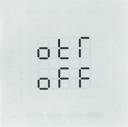
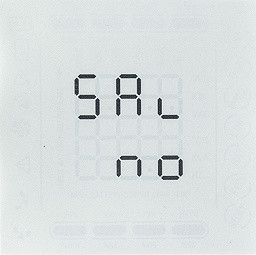
Entering the settings menu is done by pressing the left button for five seconds, and exiting without saving is done by pressing the same button for three seconds. A short (0.5 s) press switches to the next parameter.
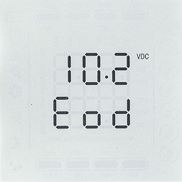
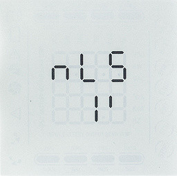
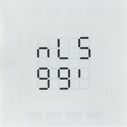
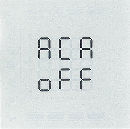
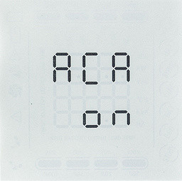
The parameter values on the screen are indicated by abbreviations that are not always easy to understand at once, but their decoding is provided in the instructions.
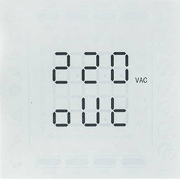
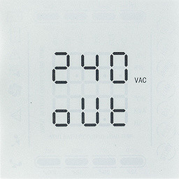
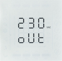
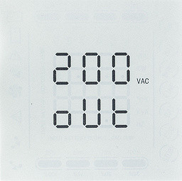
The first menu item is the selection of output voltage: 200/220/230/240 volts, with 220 V set by default.
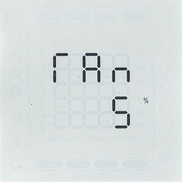
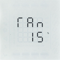
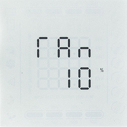
The next menu item controls the power matching when working with a generator. The parameter can be selected from 10 to 150% (the default is 100%), but the manual is not very clear. It mentions: “if the generator power does not exceed the UPS power by 50% or more, the parameter is calculated using the formula (Pgen/Pbp) * 0.9 * 100%”. Since the PSW620 has a power of 1600 watts, this implies that we are talking about generators with a power of up to 2.4 kW, which is quite low for modern generators. It is unclear what to do with generators with a power of 4-6 kW, which are much more common (and there are even more powerful models). Setting the value to “10%” is especially puzzling: according to the formula, it turns out that the generator power should be only 0.11 of the UPS power, that is, only about 260 watts for the older PSW630 model — which is unlikely for generators.
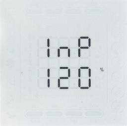
But the main thing is, what does this coordination give in practice? The description of a similar UPS, which also supports operation with a generator, states that if the total load and charge power exceeds the generator power, the charging current will be limited, and if the load decreases, the charging current will be restored. A similar rule may also apply to the PSW600 series models, but this should be clearly stated so that consumers do not have to guess and do their own experiments.
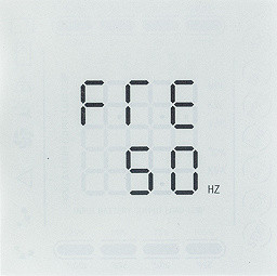
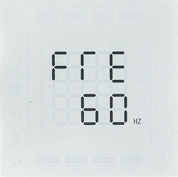
The next menu item allows you to select the nominal frequency of the power supply network — 50 (default) or 60 Hz. This is done to take into account countries with a 60 Hz standard, but in our conditions it is practically irrelevant. In linear mode, the output voltage will correspond to the input frequency — 50 Hz. For equipment designed for 60 Hz, a specialized online UPS with a frequency converter is required.
The fourth menu item controls the permissible input frequency deviations, from ±5% (default) to ±15%. This is probably intended for use with generators, as non-inverter models can have very wide frequency fluctuations. For a regular grid, a frequency deviation of ±5% is only permissible with serious reservations; according to GOST 32144-2013, the frequency should deviate by no more than ±1 Hz for 95% of the week and by ±5 Hz for 100% of the week. However, the manual does not explain this point, and does not specify what will happen if the frequency goes beyond the set limits.
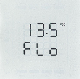
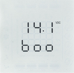
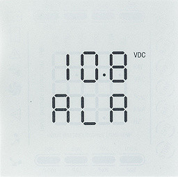
The next five menu items are related to battery settings: these include adjusting the equalize and float charge voltages, setting the low battery alarm and the full discharge alarm values that will shut off the inverter. Note that these settings are for one 12-volt battery, and different PSW600 models may have up to four such batteries.
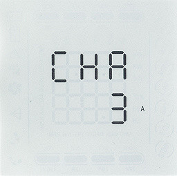
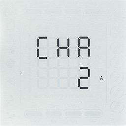
In addition, the charging current is set — 1 (default), 2 or 3 amperes for models with a built-in battery.
Having battery settings is certainly a positive thing. However, the problem is that the optimal parameters for a specific battery are often unknown, and there are no comments on this in the manual, so most users are forced to leave the default values.
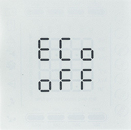
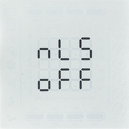
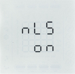
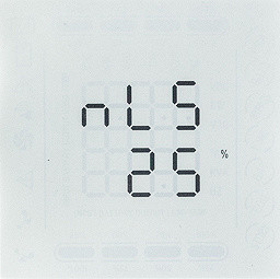
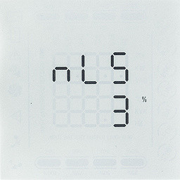
Items 10 through 13 of the menu are dedicated to the power saving mode, designed to save battery power when working with low loads. This mode can be disabled (which is done by default). If the mode is active, when operating on battery and the output consumption is below a certain threshold (depending on the combination of settings), the UPS can either go into sleep mode (which is difficult to understand from the manual) or turn off completely. When the load increases above the threshold, the device automatically exits «sleep». The threshold parameters and the interval before shutdown can be configured within a wide range.
Item 14 controls automatic switching on of the UPS (autostart) when the mains voltage appears after a low battery shutdown; by default, the source will be switched on.
Points 15 and 16 in the manual refer to the use of external chargers, such as solar panels. Since our model does not have this capability, a detailed description of these functions is not necessary. We will only note that these functions are disabled by default, and their description in the manual is not very clear.
Items 17 and 18 are intended to display the nominal input and output voltages. However, since the output voltage is set in the first menu item, it remains unclear what exactly is considered nominal for the input voltage.
Finally, point 19 is very important: it saves the changes made, for which you need to set it to “YES”.
Internal organization
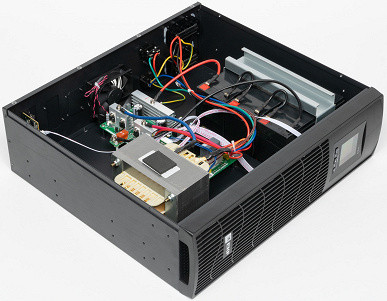
To open the case, you need to lay the UPS on its right side (from a vertical position) and unscrew the eight screws securing the left cover.
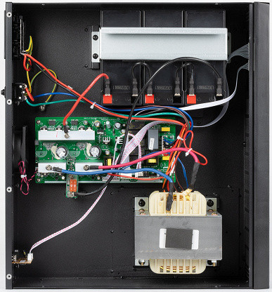
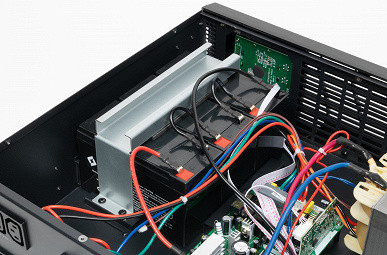
Inside the device are three series-connected batteries, secured with a U-shaped metal clamp. We also see a large AVR system transformer with a core made of Ш-shaped plates and a middle board with control and power electronics.
Replacing the batteries in the device requires considerable effort, as quick replacement is not possible and requires working with a screwdriver.
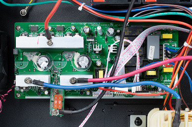
Additionally, there is a small board with USB-B and 8P8C (RJ-45) connectors and the corresponding electronic components, connected to the main board using a ribbon cable.
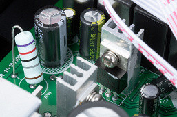
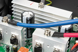
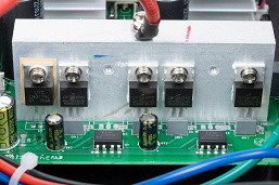
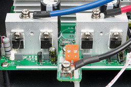
The power transistors are mounted on three aluminum radiators with fins located in parallel and directed towards each other. The fan (80x80x25 mm, 24 V / 0.19 A, exhaust, with two speeds) mainly serves this area, although the main source of heat is the AVR transformer, which heats up constantly and strongly.
The battery circuit fuses (two connected in parallel, 40 A each) are soldered to a separate small board.
Switching in the device is carried out using five Song Chuan 793-P-1C relays.
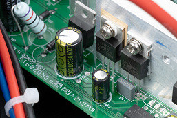
Protection against impulse interference includes two X2 capacitors (0.1 μF/310 V) and one capacitor (3.5 μF/350 V); there are no varistors in the design.
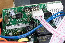
The control panel board is located inside the plastic front cover, and two cables are connected to the main board.
Battery
Our unit was equipped with a set of three Kijo JS12-9 lead-acid batteries connected in series, with a stated voltage of 12 V and a capacity of 9 Ah.
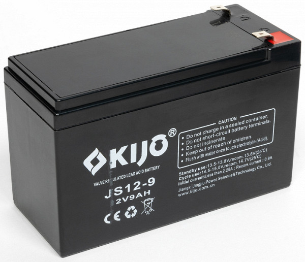
The battery capacity of 9 Ah indicated on the case refers to a 20-hour discharge, which corresponds to currents of about 0.4-0.5 A. At loads close to the maximum for the UPS, the currents can reach tens of amperes, which significantly reduces the actual capacity.
The batteries begin charging immediately after connecting the UPS to the outlet.
The optimal charging current is approximately 0.1 C, where C is the battery capacity in ampere-hours, which for this battery is 0.9 A. The permissible current can reach up to 0.3 C or 2.7 A. By default, the maximum charging current is limited to 1 ampere, but it can be increased to 3 amperes through the menu. In tests, we recorded currents of up to 1.4 A (initial values after discharge at low loads), although a current of 1.0-1.1 A was used for a long time, which leads to a moderate charging time.
The charge measurement cycle was performed after the UPS was switched off during autonomous operation with a 400 W load and the subsequent restoration of the input voltage. The results of the charging current measurements performed by the external device are given in the table.
| After 400W | Start | 3 hours | 3 hours 30 minutes | 3 hours 45 minutes | 4 hours | 4 hours 30 minutes | 5 hours and beyond |
|---|---|---|---|---|---|---|---|
| Current, A | 1,1 | 1,1 | 0.8 | 0.4 | 0.2 | 0.17 | 0.07-0.1 |
As you can see, the charging current remains at one level for a long time, and then decreases relatively quickly. Full replenishment of energy takes a little over 4.5 hours, after which the maintenance charge begins.
This indicator is average compared to other similar models. However, it is important to consider that when working with small loads, the discharge will be deeper, which will increase the charging time. We remind you that the initial charging current can be increased through the menu, which will speed up the charging process. However, this should be done taking into account the characteristics of the installed batteries: our batteries indicate «Initial current: less than 2.25A», so from the three values available in the menu, you can only choose 1 or 2 amperes, but not 3 amperes.
UPSmart Software
The software comes on a mini-CD, which cannot be downloaded from the company's website, which can be difficult: modern computers are rarely equipped with optical drives, and even old drives may not work. However, it should be remembered that this is not EKF's own development, so the distribution can be found in other sources if necessary.
The CD contains versions of the program for Windows and Linux, as well as manuals in English and Chinese.

Support is indicated up to Windows 8 and Windows Server 2012 inclusive, but we tested the program on Windows 10, which is still the most common OS. We used version 1.5, although you can find mentions of versions up to 2.5 on the Internet.
The program installation went without problems.

The interface language can only be selected between English and Chinese, although Russian versions are mentioned on the Internet.
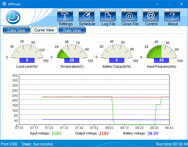
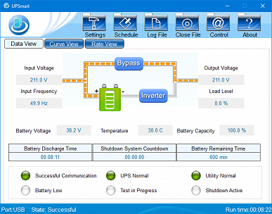
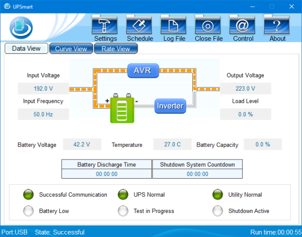
When you first start the installation wizard, it prompts you to select the type of UPS (single-phase or three-phase) and specify whether it is connected via USB or COM port, as well as the number of 12-volt batteries. After connecting the UPS to the computer's USB port, an animation is displayed demonstrating the distribution of energy flows.
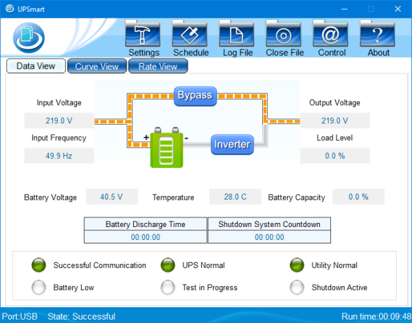
Also displayed are the input and output voltages, input frequency, battery voltage, load level as a percentage of maximum, and the internal case temperature. The battery capacity, indicated in the «Battery Capacity» field, is shown as zero, despite being almost fully charged — a solution to this problem will be discussed below.
In addition, information fields are available, such as the total battery life (not the time until shutdown at the current charge and load levels) and the remaining time before the OS shutdown signal (default 5 minutes). There are also six indicators that display additional aspects, such as low battery level.
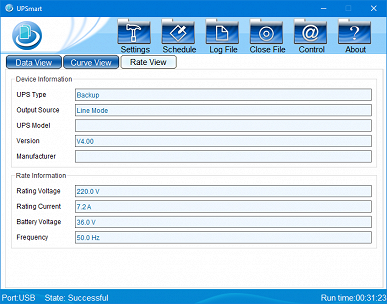
You can switch to display the information in the form of graphs or a table.
When Auto Voltage Regulation is triggered, the image as a whole does not change, only the word Bypass at the top of the diagram changes to AVR:
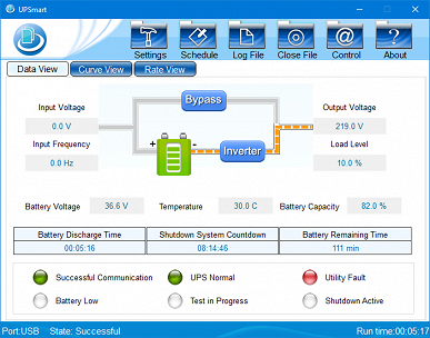
Switching to battery power changes the picture accordingly:
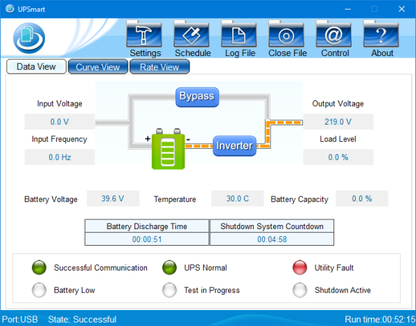
Changes in the program are applied with a delay of about a second.
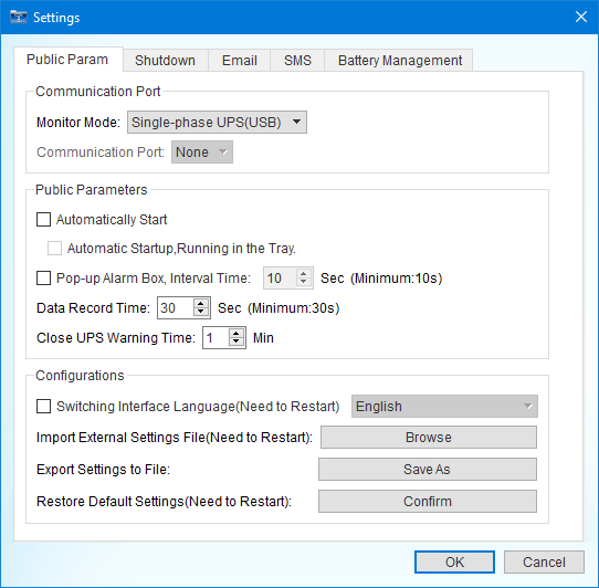
The «Settings» button at the top of the window opens the settings menu. On the first tab, you can set the program to autoload when Windows starts and configure the display of pop-up messages about critical events at a specified interval.
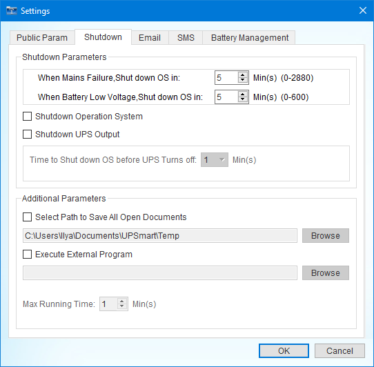
The second tab allows you to set a delay before sending a command to shut down the operating system depending on two factors: problems with the external network (from 0 to 2880 minutes) and reaching a low battery level (from 0 to 600 minutes). Since the program is universal and is not tied to a specific UPS model, the setting ranges are selected in general terms. For the PSW620 model, they may be surprising: 600 minutes is ten hours, which exceeds the battery life of this model even with a full charge and minimal load.
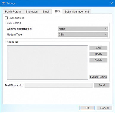
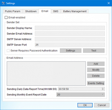
The third and fourth tabs are dedicated to sending notifications by e-mail or SMS.
On the fifth tab, you can specify some battery parameters, and it is better to do this: then the “Battery Capacity” field of the main program window will no longer display zeros.
The «Schedule» button allows you to set up a schedule for turning the UPS on and off, but for our model this will not mean power management of connected devices, since the output sockets always have voltage when there is voltage at the input.
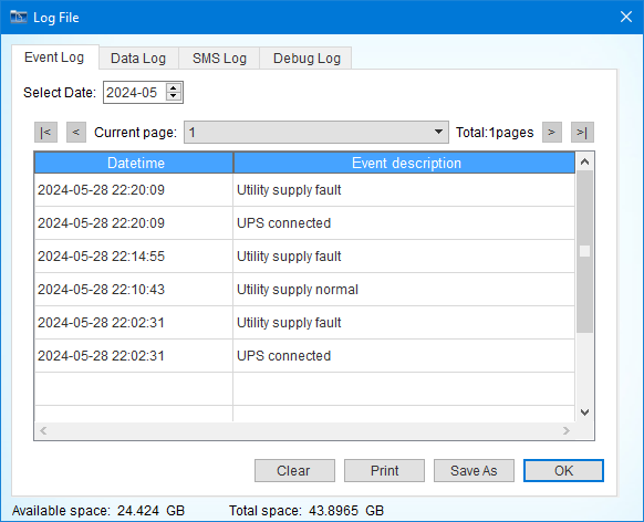
The purpose of the «Log File» button is obvious — to view the list of events.
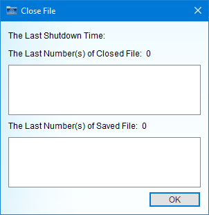
«Close File» is the time of the last OS shutdown after the program issued the corresponding command and the count of files closed and saved at the same time.
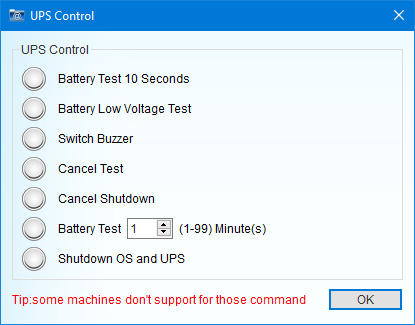
Using «Control» you can perform some actions — run a battery test, shut down the OS, turn off sound signals, etc.
It should be noted that the PSW600's audible warning scheme is not intrusive. Unlike most other models, which often emit shrill beeps, here, after switching to battery mode, there are short, infrequent beeps for the first minute. Then the UPS becomes quiet and only starts beeping frequently shortly before shutting down when the battery charge gets low, again for one minute. Thus, forced muting does not seem necessary.
Testing
Clarifications to the specification
First, let's clarify a few important points, some of which are listed in the specification, but require verification:
- Smart Battery support: When the UPS is connected to the USB port of the computer, the «HID UPS Battery» device does not appear, which indicates that Smart Battery is not supported and it is not possible to turn off the computer using this mechanism.
- Low-load battery operation: As mentioned earlier, with the default settings, the UPS successfully operated autonomously without a load for 30 minutes.
- Cold start: The UPS can be started by applying voltage to the outputs even if there is no power at the input. To do this, you need to hold down the left and middle buttons for a long time, and not until the display backlight appears.
- Compatibility with APFC loads and PSUs: We checked compatibility by connecting a mid-range computer with a be quiet! Straight Power 10 (500 W, APFC) power supply. When working in office applications, the consumption was 150-230 VA (with the monitor), no problems arose.
- Own consumption: With a fully charged battery and no load, the source consumes 40-41 W (48-49 VA, PF = 0.83), and when turned off — about 39 W (48 VA, PF = 0.82). When starting to charge a battery discharged to auto-off at a load of 400 W, the consumption increases to 75 W (81 VA, PF = 0.92).
Output voltage waveform
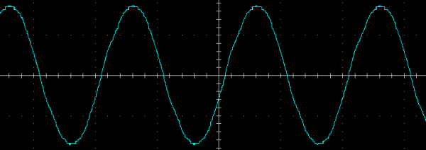
The output voltage when operating from a battery is a sine wave, here is its appearance at idle and at a purely active load of 200 W, the horizontal division value here and below is 5 ms:
Without load
Overall the results are good, but on closer inspection you can see some slight distortion in the sine wave shape. Without load the total harmonic distortion of the voltage was 2.8%, and with load it varied from 2.5% to 2.7% in the range from 200 W to 1 kW.
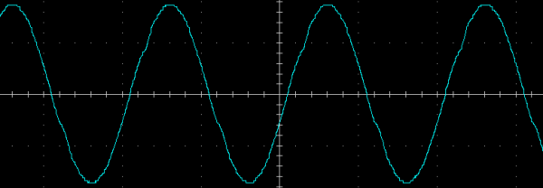
Active load 200 W
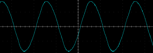
Active load 1000 W
At a load of 400 VA with a reactive component (PF = 0.7), the sine wave is not so beautiful, distortion is at the level of 7.1%, which still meets the requirements of GOST 32144-2013, which allows no more than 8%.
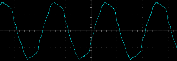
Load 400 VA with reactive component (PF = 0.7)
As for the load increase, we cannot estimate the impact due to the lack of calibrated loads with a reactive component at higher values.
The specification for the EKF E-Power PSW600 UPS indicates a nonlinear distortion coefficient (NDC) of no more than 5%, without specifying the type of load. For active loads, this value is true, but for reactive loads it may be different.
The frequency deviation is ±1 Hz, which meets the requirements of GOST without additional reservations.
Temperature conditions, noise
The UPS heating can be monitored either via the indicator on the device (or in the UPSmart program) or by measuring the temperature of the case surfaces. In both cases, even under significant loads, the case temperature does not exceed 10-12 degrees above room temperature.
However, the internal components heat up much more. Thus, the AVR system transformer can reach a temperature of 25-27 degrees above ambient, regardless of the mode and load, and the inverter radiators — 15-18 degrees. These measurements were taken with the cover removed, and when assembled, the temperature readings may change slightly.
The greatest heating is observed in the lower part of the case, where the transformer is located. The fan mainly covers the area with the inverter power elements, which can explain the moderate heating of the components. Under heavy loads, the battery life is limited, and the components do not have time to heat up much. Under light loads, the transistor temperature also remains low.
The main source of noise is the fan. It has two speeds: at the lower speed, the noise level is 41 dBA at a distance of 1 meter, which is slightly below average for a UPS, but at the higher speed, the noise increases to 45.5 dBA, which is already above average. The fan emits sound at frequencies of about 260-280 Hz at the lower speed and 370-390 Hz at the higher speed, which makes it noticeable and not easily masked in a typical office environment.
Autonomous work
Let's move on to testing battery life with different loads. Here are the results in the form of a graph:
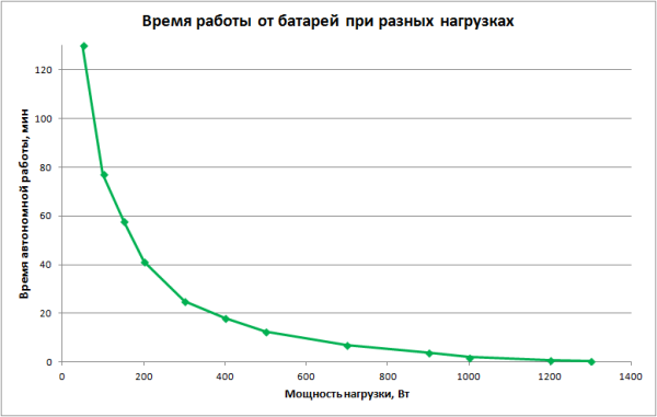
More precise values are given in the table:
| Load, W | Battery life, h:mm:ss |
|---|---|
| 50 | 2:09:56 |
| 100 | 1:17:05 |
| 150 | 0:57:59 |
| 200 | 0:41:21 |
| 300 | 0:24:57 |
| 400 | 0:18:05 |
| 500 | 0:12:31 |
| 700 | 0:07:06 |
| 900 | 0:03:50 |
| 1000 | 0:01:58 |
| 1200 | 0:00:48 |
| 1300 | 0:00:31 |
Power measurements above 1300 watts were not carried out due to the lack of corresponding calibrated loads, so the overload capacity was also not investigated. However, it is already obvious that the battery life at a consumption approaching the maximum 1600 watts will be only a few seconds, up to a minute at most. The specification on the website states that the UPS provides two minutes of battery life at full load, although there is no such information in the instructions.
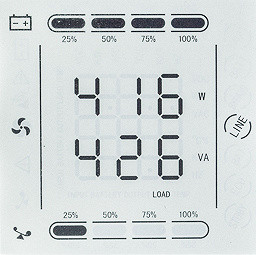
The power rating on the display is generally true, except that for a purely active load there may be slight discrepancies between the values in watts and volt-amperes.
Automatic output voltage regulation
The UPS is equipped with a two-stage AVR system, one stage (step-up) is triggered when the input voltage decreases, and the second (step-down) when it increases.
We present the results when operating at a load of 200 W at a nominal output voltage of 220 V.
| Input voltage (from 290 to 0 V) | Output voltage | Working hours |
|---|---|---|
| 290-269 V | 218-219 B | from battery |
| 268-235 V | 228-200 V | from the network with reduction (AVR) |
| 234-201 B | 234-201 B | directly from the network |
| 200-167 V | 231-196 B | from the network with increase (AVR) |
| 166 V and less | 218-219 B | from battery |
| Input voltage (from 0 to 290 V) | Output voltage | Working hours |
| less than 174 V | 218-219 B | from battery |
| 175-213 V | 200-243 V | from the network with increase (AVR) |
| 214-242 V | 214-242 V | directly from the network |
| 243-281 B | 208-240 V | from the network with reduction (AVR) |
| 282-290 V | 218-219 B | from battery |
To evaluate the UPS, we are guided by GOST 29322-2014, which allows a deviation from the nominal voltage of 220 V within ±10%, which corresponds to a range from 198 to 242 V. The specification specifies a deviation of ±5%, that is, the output voltage should be in the range from 209 to 231 V.
The lowest recorded value was 196 V, which is 11% less than the nominal 220 V — this does not contradict GOST, but significantly exceeds the specification. The maximum value reached 242 V, which is 10% more than the nominal — this complies with GOST, but again exceeds the specification.
Thus, despite the discrepancy with the specification, the GOST standard remains an important criterion, and output voltage deviations can be considered within the normal range.
For the output voltage of 220 V, the declared input voltage range in the stabilization mode (without switching to the battery) is from 165 to 280 V. Our observations confirm that this range corresponds to the declared one, although it is worth considering the difference between the values for switching to the mode and returning from it. This difference, called «hysteresis», is necessary to prevent frequent switching of the source between modes with small fluctuations in the input voltage.
Transient processes
The specification states that the switching time should be no more than 10 ms, but does not specify what kind of switching is meant. Possible options include: switching from AVR to direct feed of the input mains, from inverter to feed, the reverse, and also switching from inverter to one of the AVR stages, for example when the input voltage is first reduced to 160 V and then restored to 190-195 V.
So it should be assumed that any switching should occur within 10 ms. Below are waveforms for 100 W and 200 VA loads (PF = 0.7), where one division on the horizontal axis corresponds to 5 ms.
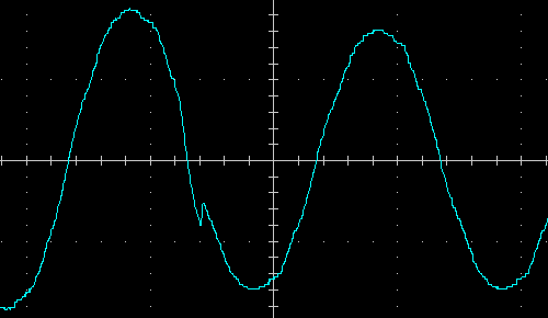
Transition from direct broadcast to step-down AVR, 100W load
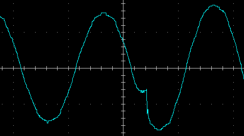
Transition from AVR step-down to direct broadcast, 100W load
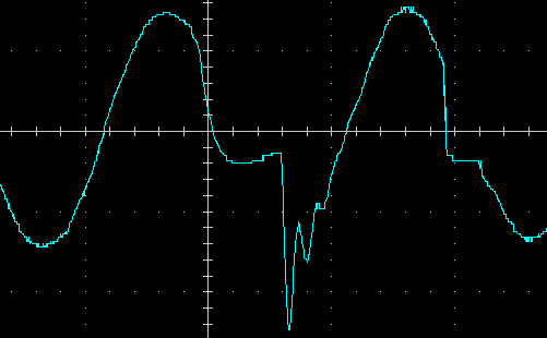
Transition from AVR step-up stage to battery, 100W load
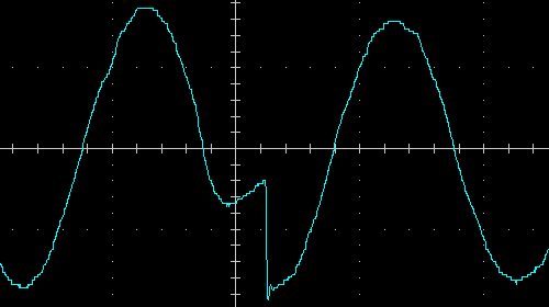
Transition from battery to step-down AVR, 100W load
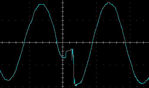
Transition from battery to AVR step-up stage, 100W load
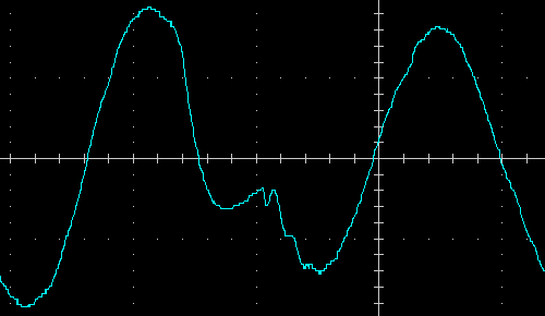
Transition from AVR step-down to battery, 100W load
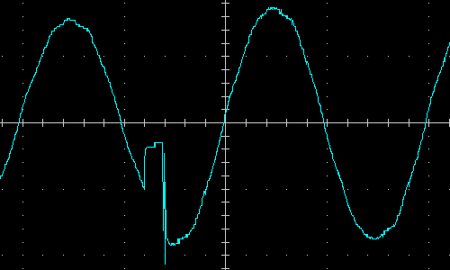
Transition from direct broadcast to AVR step-up stage, 100W load
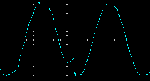
Transition from battery to AVR step-up stage, 200VA load (PF=0.7)
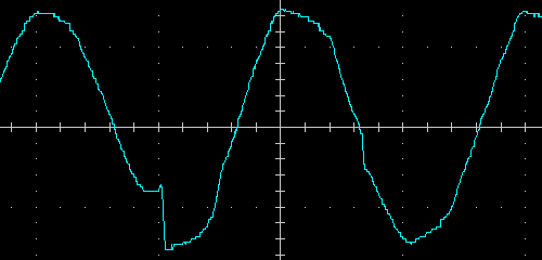
Transition from AVR step-up stage to battery, 200VA load (PF = 0.7)
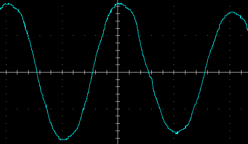
Transition from AVR step-up stage to direct transmission, 200 VA load (PF = 0.7)
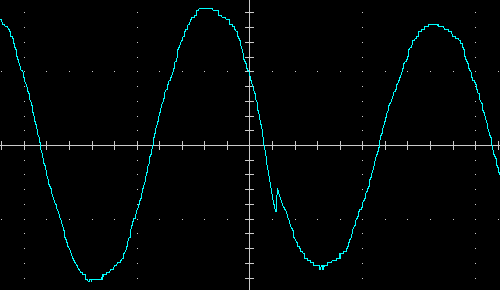
Transition from direct transmission to step-down AVR, load 200 VA (PF = 0.7)
Transient processes usually take no more than 3-5 milliseconds, sometimes the switching moment is difficult to determine on the oscillogram. All cases correspond to the declared interval of 10 ms.
Contact bounce is usually insignificant, and only occasionally short but noticeable bursts are observed.
Summary
The EKF E-Power PSW620-RTB uninterruptible power supply is a universal solution for floor, desktop or rack mounting, with accessories for both installation options.
Cons:
- LCD display: its readability at some viewing angles leaves much to be desired, which is a common drawback for many similar devices.
- Replacing batteries: the process is labor-intensive, especially in rack mounting, although the frequency of such replacements is low.
- Poor presentation of information: the user may need time to independently analyze all the functions or contact technical support to get full access to all the capabilities of the device.
Pros:
- Software: despite its archaism, it performs functions no worse than software from other UPS manufacturers.
- Compliance with GOST: testing parameters comply with standards, although not all completely match the specification.
- Functionality: The display and software provide enough information for everyday use, and six output sockets cover most needs.
- Charging time: With default settings, charging the battery takes an average time, but it can be accelerated by increasing the charging current in the settings.
- Temperature and noise: The unit has moderate heating in various modes and, despite the possible high noise level, it is not intended for installation in the bedroom.
The presence of several models in the line allows you to choose a UPS that meets both your power needs and the installation option.

